1
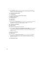
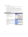
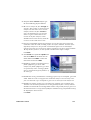
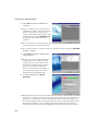
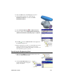
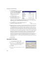
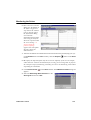
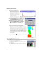
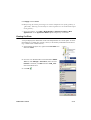
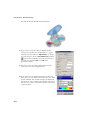
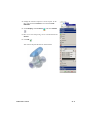
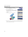
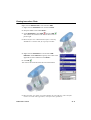
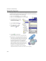
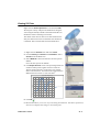
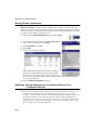
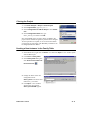
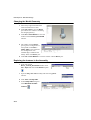
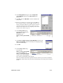
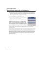
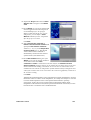
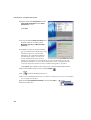
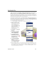
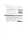
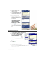
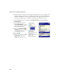
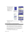
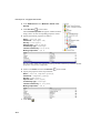
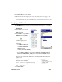
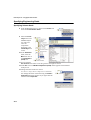
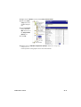
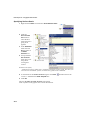
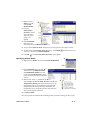
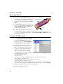
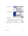
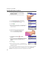
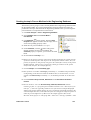
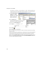
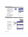
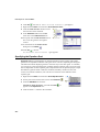
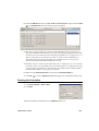
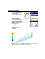
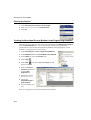
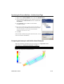
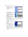
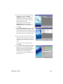
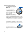
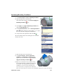
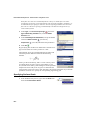
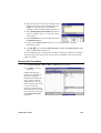
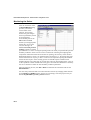
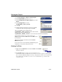
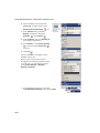
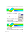
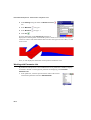
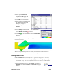
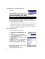
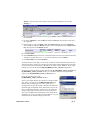
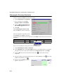
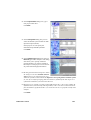
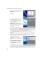
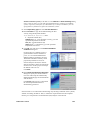
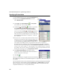
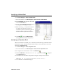
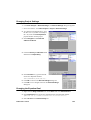
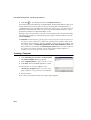
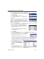
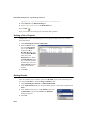
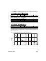
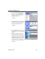
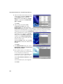
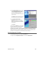
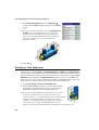
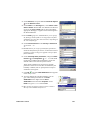
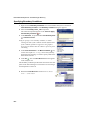
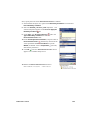
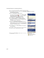
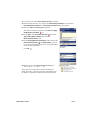
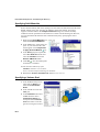
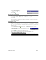
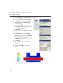
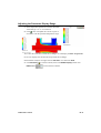
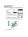
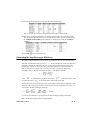
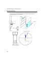
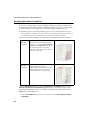
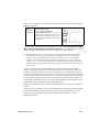
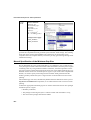
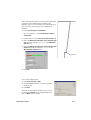
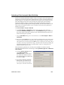
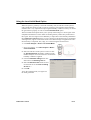
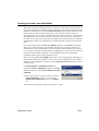
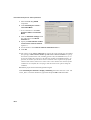
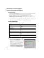
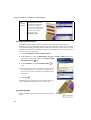
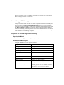
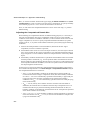
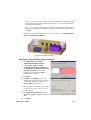
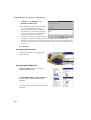
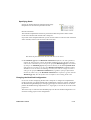
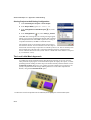
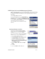
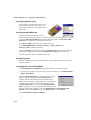
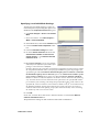
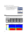
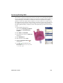
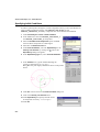
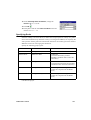
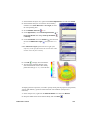
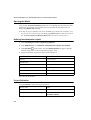
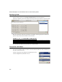
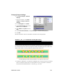
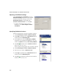
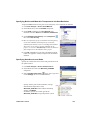
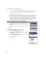
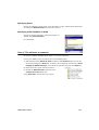
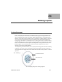
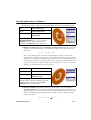
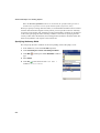
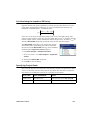
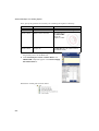
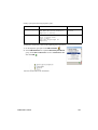
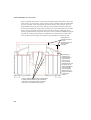
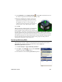
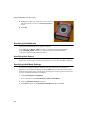
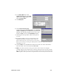
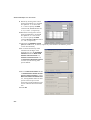
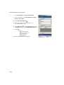
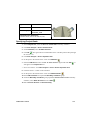
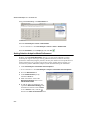
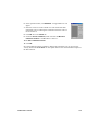
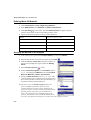
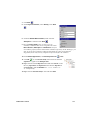
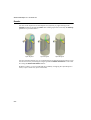
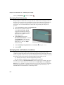
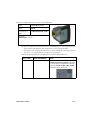
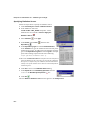
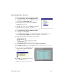
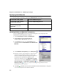
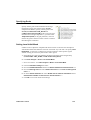
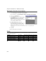
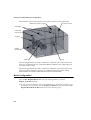
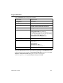
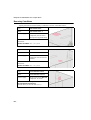
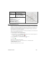
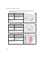
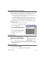
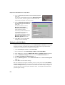
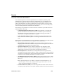
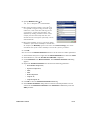
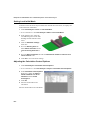
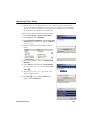
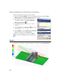
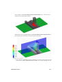
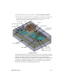
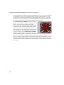
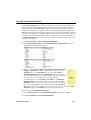
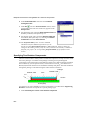
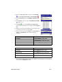
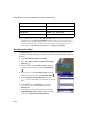
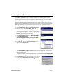
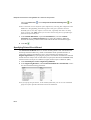
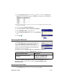
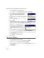
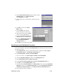
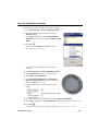
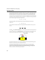
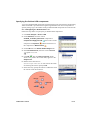
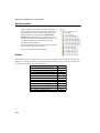
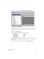
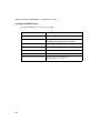
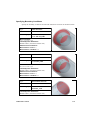
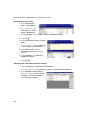
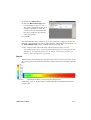
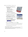
First Steps: A1 - Ball Valve Design 1 In the FloEFD Analysis tree, right-click the Boundary Conditions icon and select Insert Boundary Condition. 2 Select the inner face of the LID_1 part as shown. (To access the inner face, set Filter to Geometry and right-click the Lid_1 until the inner face is highlighted, then click the left mouse button). 3 Select Flow Openings 4 Set the Mass Flow Rate and Inlet Mass Flow. to 0.5 kg/s. 5 Click OK . The new Inlet Mass Flow 1 item appears in the FloEFD Analysis tree. With the definition just made, we told FloEFD that at this opening 0.5 kilogram of water per second is flowing into the valve. Within this dialog we can also specify swirling of the flow, a non-uniform profile and time-dependent properties of the flow. The mass flow rate at the outlet does not need to be specified due to the conservation of mass; inlet mass flow rate equals outlet mass flow rate. Therefore, a different condition must be specified, such as outlet pressure. A1-6