1
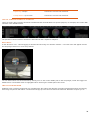
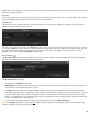
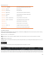
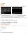
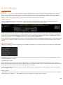
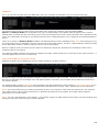
VCR. This mode can be used for testing, reviews or e.g. audio sync on SDI. Note that also clicking the Connect button while
holding down the Quick key: Ctrl will switch the PLAYOUT module in Emulate-mode.
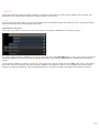
SDI ANCILLARY DATA (ANC)
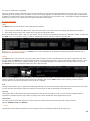
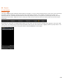
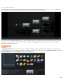
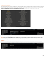
SCRATCH uses the NVIDIA drivers to embed Ancillary metadata (ANC) inthe SDI signal. This option is enabled by default. To
switch it off you need to set the SConfig variable AS_ENABLE_SDI_ANC=FALSE. There are four ancillary data tracks available
for adding timecode data - VIDC, LTC, Film Timecode and Production Timecode. By default SCRATCH embeds the timeline
timecode to VIDC, the shot timecode to LTC and replicates both timecode in the Film- and Production tracks. You can change
which timecode is assigned to which track by switching the Regenerate option on the Playout menu panel from Rec-TC to TC.
SDI EMBEDDED AUDIO
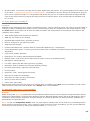
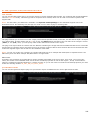
An NVIDIA SDI card with firmware 3.09 or higher supports embedding audio in the SDI signal. As was discussed in Chapter 5
- The Player, you have a separate set of audio settings for Playout. Selecting the SDI Embedded device will include the audio
played in the SDI signal available for recording by the VTR.
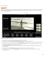
02 - Control Surfaces
GENERAL
The external control surfaces are a great way to increase the speed of color grading in SCRATCH. There current supported
panels are: Tangent Devices (CP200, Wave and Elements) and AVID Euphonix (MC Color).
Note: Both the Tangent Elements and AVID Euphonix require you to install their own driver and communication layer
application software that comes with the panel.
PHYSICAL CONNECTIONS
USB/SERIAL INTERFACE
To Connect the Tangent Wave using the USB/Serial interface, simply power on the device and connect the USB cable to an
available USB port on the SCRATCH system. Once connected, the device installs itself automatically, including (if needed) a
Virtual COM port (VCP) driver to connect to the JL Cooper device. From here you can proceed to the section on
CONFIGURING THE CONTROL SURFACES. If, after following the steps to configure the control surface, you still are not able
to establish communication with the device, see the section about TROUBLESHOOTING CONTROL SURFACE PROBLEMS for
more details, later in this chapter.
ETHERNET INTERFACE
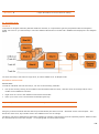
In an Ethernet configuration, each control surface is assigned an IP address on the network. This IP address identifies the
control surface on the network, so that SCRATCH can communicate with it. In most cases, this really just means the control
surfaces and computer must have the same first three numbers in the IP address. For example, 192.168.10.xxx. This will be
covered in detail in the section about CONFIGURING THE CONTROL SURFACES later in this chapter.
The control surfaces need to be on the same physical network as the system but can also be connected directly to the
system in a stand-alone setup or if there is a second network adapter available in the SCRATCH system. It’s recommended
that you keep the control surfaces as close to the computer on the network as possible. Meaning, there are a minimal
number of network switches or other network appliances in between them. If necessary, consult a network administrator or
IT manager for proper network setup between the SCRATCH computer and the Ethernet control surfaces.
If the network has a DHCP server that assigns IP addresses, it is possible to just use this to assign the IP address to the
control surfaces. If however, there is no DHCP server, or if you are connecting the control surfaces directly to the computer
and there is no other network connection needed, assigning the IP addresses manually is recommended.
261