1
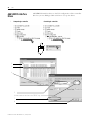
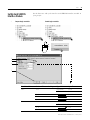
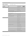
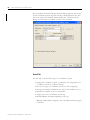
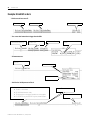
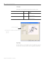
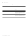
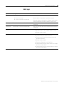
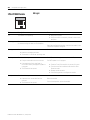
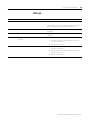
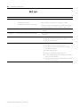
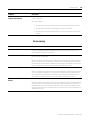
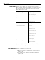
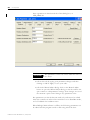
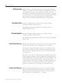
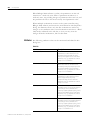
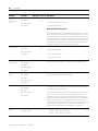
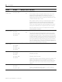
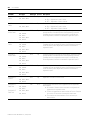
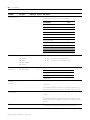
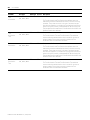
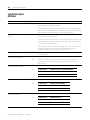
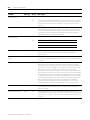
Axis Attributes
Attribute
Axis Type
Data Type Access Description
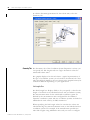
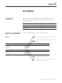
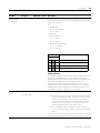
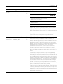
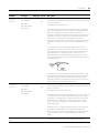
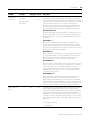
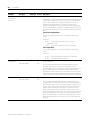
Acceleration
Feedforward
Gain
AXIS_SERVO
REAL
AXIS_SERVO_DRIVE
GSV
SSV
261
%
AXIS_SERVO
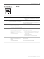
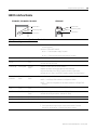
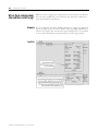
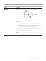
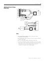
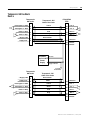
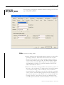
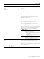
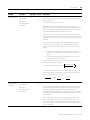
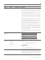
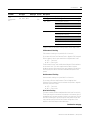
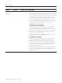
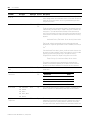
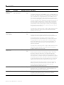
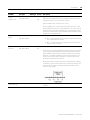
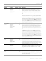
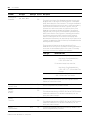
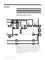
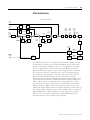
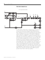
When you connect to a torque servo drive, use the Acceleration
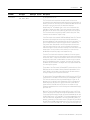
Feedforward Gain to give the Torque Command output necessary to
generate the commanded acceleration. It does this by scaling the
current Command Acceleration by the Acceleration Feedforward Gain
and adding it as an offset to the Servo Output generated by the servo
loop. With this done, the servo loops do not need to generate much of a
contribution to the Servo Output, hence the Position and/or Velocity
Error values are significantly reduced. Hence, when used in conjunction
with the Velocity Feedforward Gain, the Acceleration Feedforward Gain
lets the following error of the servo system during the acceleration and
deceleration phases of motion be reduced to nearly zero. This is
important in applications such as electronic gearing and synchronization
where the actual axis position must not significantly lag behind the
commanded position at any time.
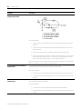
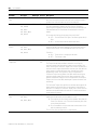
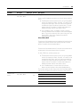
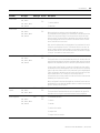
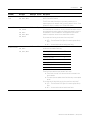
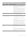
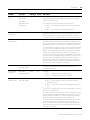
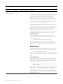
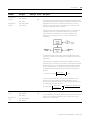
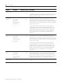
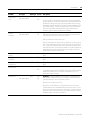
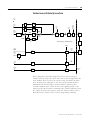
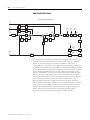
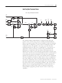
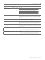
When you connect to a velocity servo drive, use Acceleration
Feedforward to add a term to the Velocity Command that is proportional
to the commanded acceleration. This can be effective in cases where
the external drive shows a steady-state velocity error during
acceleration and deceleration.
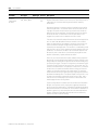
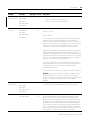
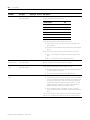
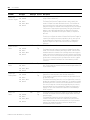
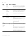
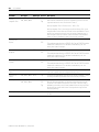
The best value for Acceleration Feedforward depends on the drive
configuration. Excessive Acceleration Feedforward values tend to
produce axis overshoot. For torque servo drive applications the best
value for Acceleration Feedforward is theoretically 100%. However, the
value may need to be increased slightly to accommodate servo loops
with non-infinite loop gain and other application considerations. For
velocity servo drive applications the best value for Acceleration
Feedforward is highly dependent on the drive’s speed scaling and servo
loop configuration. A value of 100%, in this case, means only that 100%
of the commanded acceleration value is applied to the velocity
command summing junction and may not be even close to the optimal
value.
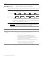
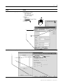
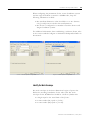
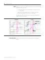
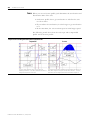
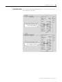
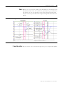
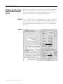
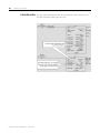
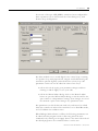
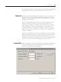
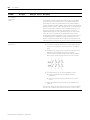
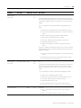
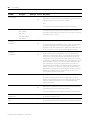
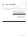
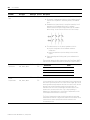
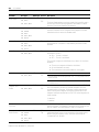
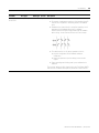
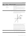
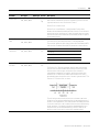
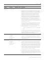
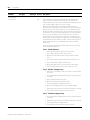
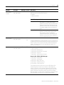
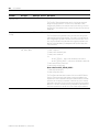
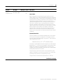
To find the best Acceleration Feedforward Gain, run a simple project that
jogs the axis in the positive direction and monitors the Position Error of
the axis during the jog. Usually Acceleration Feedforward is used in
tandem with Velocity Feedforward to achieve near zero following error
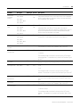
during the entire motion profile. To fine tune the Acceleration
Feedforward Gain, the Velocity Feedforward Gain must first be optimized
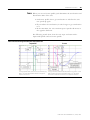
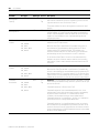
using the procedure described above. While capturing the peak Position
Error during the acceleration phase of the jog profile, increase the
Acceleration Feedforward Gain until the peak Position Error is as small
as possible, but still positive. If the peak Position Error during the
acceleration ramp is negative, the actual position of the axis is ahead of
the command position during the acceleration ramp. If this occurs,
decrease the Acceleration Feedforward Gain such that the Position Error
is again positive. To be thorough the same procedure should be done for
the deceleration ramp to verify that the peak Position Error during
deceleration is acceptable. Note that reasonable maximum velocity,
acceleration, and deceleration values must be entered to jog the axis.
Continued on next page
Publication LOGIX-UM002B-EN-P - January 2007