1
R
Creating New Peripherals
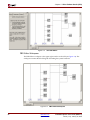
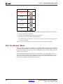
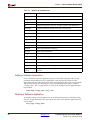
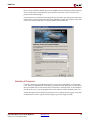
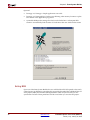
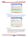
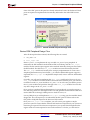
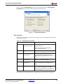
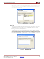
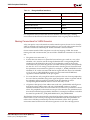
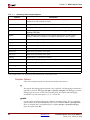
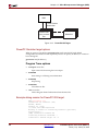
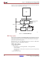
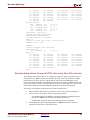
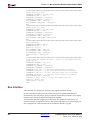
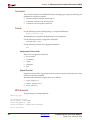
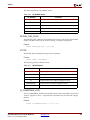
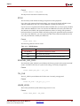
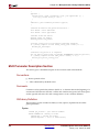
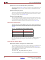
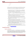
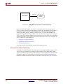
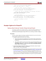
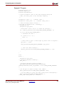
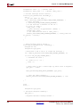
Figure 4-7: Configure Address Ranges
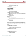
You will need to indicate the number of address ranges, and the size (byte, half-word and
word) of the data being accessed. We recommend the size of these registers be the same as
the data-width of the bus to which it is connected, 32 bits for OPB peripherals and 64 bits
for PLB peripherals. This will allow for a smaller implementation of the IPIF by optimizing
out the implementation of the byte-steering logic.
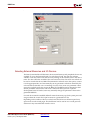
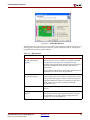
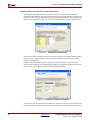
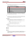
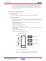
An enable signal is generated for each range, rather than each word in the address space
supported by the peripheral. (Note that this is different from the case of software
addressable registers where a enable signal is generated for each register.)
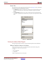
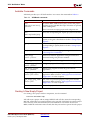
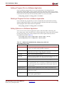
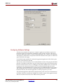
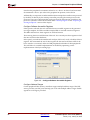
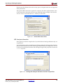
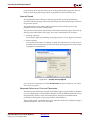
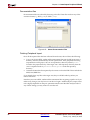
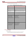
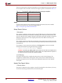
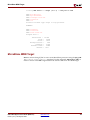
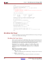
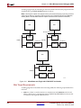
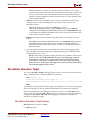
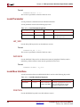
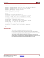
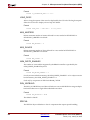
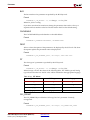
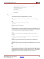
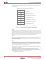
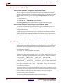
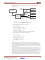
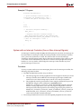
Figure 4-8:
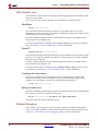
Configure the IPIC
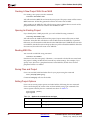
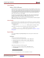
Configure the IPIC
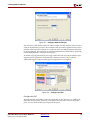
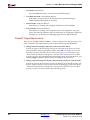
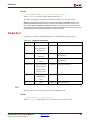
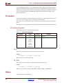
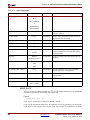
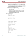
Typically the IPIC generated by this tool is dependent on the selections you make in the
Select IPIF Services panel. However, some expert users may want access to other IPIC
ports. You can check off these special ports in this panel.
Embedded System Tools Guide (EDK 6.2i)
UG111 (v1.4) January 30, 2004
www.xilinx.com
1-800-255-7778
85