1
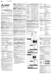
1.1 Searching for Faults Automatically ••• Full Auto Mode/Auto Mode
In the Full Auto mode, the optimum Distance range and Pulse width values are
found by the MW9070B. In the Auto mode, measurment is performed using the
values for these parameters set at the Setup screen.
For details, see section 4.1.
Measurement Conditions
Search Results
Appendixes Maintenance Performance Test
Operation
Setting Up
Trace Waveform
Before Use
In this mode, faults in the cable are detected and displayed after about 3 minutes
just by pressing the [Start] key. Set the measurement mode at the Setup screen to
Full Auto or Auto, then the following screen is displayed when measurement is
finished. Faults are indicated by the
(event) symbol and the fault data is displayed under the waveform. The faults are called events and this display is called
an Event Table.
Outline
1.1 Searching for Faults Automatically •••Full Auto Mode/Auto Mode
Event Table
• Trace Waveform
The trace waveform is displayed with the attenuation on the yaxis and the distance on the x-axis. The left end of the trace
display is the OTDR optical output and the right end is the far
end of the fiber cable. The
symbol is displayed at faults in
the cable.
• Measurement Conditions
Index
Light Wavelength (λ), Distance Range (DR), Pulse Width
(PW),
Index of Refraction (IOR), Number of Averagings (Average)
• Search Results
Total number of Faults (Total), Total Fiber Length (Fiber
Length), Total Loss of Entire Fiber (Total Loss)
• Event Table
Number of Fault counted from Left (No.), Distance from
OTDR (Position), Splice Loss, Return Loss (R. Loss), Total
Loss to the Fault (T. Loss)
3