1
Model 8904A
Adjustments
Section 5
ADJUSTMENTS
5-1. INTRODUCTION
This section contains adjustments and checks that assure peak performance of the Multifunction
Synthesizer. The instrument should be readjusted after repair or failure to pass a performance test.
Allow a 10 minute warm-up prior to performing the adjustments. Removing the top and bottom covers
is the only disassembly required for most adjustments on a standard instrument. An instrument with
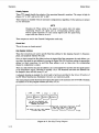
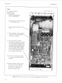
two outputs, Option 002, will require removing the A10 Output Assembly if the A3 Output Assembly
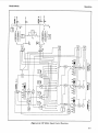
requires adjustment. (The disassembly procedure is shown in Figure 5-4.)
NOTE
The instrument has been fully tested and calibrated prior to shipment. I t is
preferable that m adjustments be made to the instrument unless it has failed
during performance testing (see Section 4).
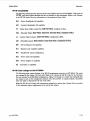
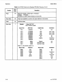
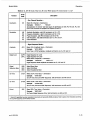
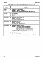
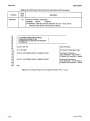
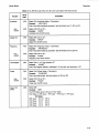
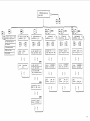
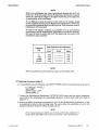
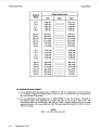
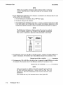
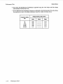
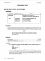
To determine which performance tests and adjustments to perform after a repair, refer to paragraph 54, Post-Repair Tests, Adjustments, and Checks.
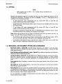
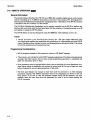
5-2. SAFETY CONSIDERATIONS
This section contains information, cautions, and warnings which must be followed for your protection
and to avoid damage to the equipment.
This instrument contains components that are highly susceptible to damage
from static discharge. Always observe proper ESD safety procedures while
making any measurements or touching any part of the inside of the
instrument.
Most adjustments described in this section are performed with power supplied
to the instrument and with protective covers removed. Maintenance should
be performed only by service trained personnel who are aware of the hazard
involved (for example, fire and electrical shock). Where maintenance can be
performed without power applied, the power should be removed.
Removal of the Multifunction Synthesizer’s top and bottom covers is necessary
to perform these adjustments. The exposed power supply contains circuitry
operating at a potential of ~ 1 6 0Vac. Be very careful to not rest your hands,
tools, or anything else against any part of the power supply.
Immediately below the top of the rear frame rail are the line-power socket,
fuse holder, and line-voltage-select switch. If the instrument must be moved
while being adjusted, be careful not to let your fingers touch the terminals on
any of these parts while moving.
5-1