1
6.2.14 Holding the piston by the larger “head” end, dip the other end into a container
of clean operating fluid, and transfer to the bore in the underside of the
cylinder. Allow the fluid to run through the bore. Repeat this 2 or 3 times to
ensure a good film of clean operating fluid exists in the cylinder bore.
6.2.15 Carefully introduce the piston into the underside of the cylinder, and push
gently through.
6.2.16 NEVER FORCE THE PISTON INTO ITS CYLINDER OR DAMAGE WILL RESULT.
If resistance is felt, introduce more fluid. If resistance continues, re-clean
piston, cylinder or both. If, after repeated cleaning, the piston still will not slide
freely within the cylinder, then permanent damage may have occurred. In
which case, the parts should be returned to the factory for evaluation or
replacement.
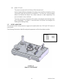
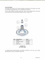
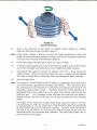
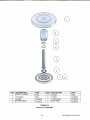
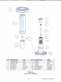
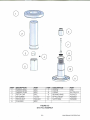
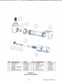
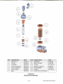
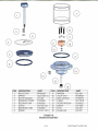
6.2.17 Insert piston/cylinder assembly into piston nut (5) through the threaded end,
such that the shoulder on the cylinder is located within the central bore of the
nut.
6.2.18 Replace piston cap (4), and secure with set screw (3), DO NOT OVERTIGHTEN.
6.2.19 Carefully screw the assembly into the instrument, ensuring that the o-ring (10)
is clean and undamaged, and correctly fitted to the piston post (11).
6.2.20 Replace weight carrier assembly (1 & 2), ensuring that it locates correctly on
the piston cap.
Replacement PCU Assembly
Note: The piston and cylinder are a matched pair, which is calibrated and adjusted
to a calculated mass figure. If, for any reason, the piston or cylinder becomes
damaged, then the entire assembly must be replaced. The replacement
assembly consists of the following components: Item numbers 1 through 8.
6-5
MAINTENANCE & SERVICING