1
INPUTS Cont.
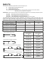
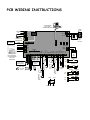
KEYSWITCH - This input can be used to control the panel via a key switch, digital keypad or similar. This is a
multi-state input which can be end-of-line configured in the same way as the 8 zone inputs. These multiple end-ofline configurations will produce either set/unset or stay mode on/off on an individual partition basis.
TAMPER - A 24Hr tamper circuit is available for monitoring tamper status of detectors, junction boxes, cabinets
and satellite sirens etc. This Tamper circuit is programmable with 2 options (P311E1E) either normally closed loop
or 2k2 EOL supervision. The tamper circuit must be terminated with an end-of-line resistor if 2k2 EOL supervision
is selected. The activation events and outputs for this tamper circuit are mapped in the same manner as for
detection zones 1-8.
AC - Connect the two low voltage wires (no polarity) from the transformer to the terminals marked AC on the Elite
PCB. The PW16 includes a transformer rated at 1.4 amps at 17 volts and incorporates an inbuilt thermal
protection fuse.
EARTH - Always connect the mains earth to the appropriate terminals on the mains terminal block in the steel
cabinet. Also connect a lead from this earth point to the terminal marked "Earth" on the Elite PCB.
BATTERY - Connect a sealed lead acid rechargeable 12V d.c. battery to these red and black battery leads. The
minimum recommended battery capacity is 7 amp hours. Battery charge current at these terminals is limited to
300mA maximum.
LINE IN - This pair of terminals is used to connect the PW16 to the incoming telephone line from the street. The
communicator uses this line for reporting.
LINE OUT - This pair of terminals is used to connect telephones and other communication equipment to the
incoming phone line via the PW16 controller. The telephone line is passed through the PW16 controller to ensure
that the line is available to the controller when it is required. Full details regarding the communicator can be found
in a separate section.
OUTPUTS
12 VOLT OUTPUTS - There are four 12 volt dc outputs available on the PW16 PCB. They are fuse protected
suitable for powering detectors, sirens and other external devices. These outputs are marked 12v and 0v, and are
supplied by fuses F1 and F2. A maximum total load of 1 amp may be drawn from these terminals. The fourth set of
fused (F2) 12V terminals are found adjacent to the keypad comms clock and data terminals.
OUTPUTS 1 & 2 - These fully programmable, high current, open collector (high-going-low) type FET outputs are
capable of switching up to 1.5A @ 12V d.c. These 2 outputs are normally set as switched outputs ,providing power
for 12v sirens or piezos. However If options 2 or 3 are turned Off at address P310E (2 relating to output 1 and 3
relating to output 2) then the output becomes a siren output designed to drive an 8 ohm 10 watt horn speaker with a
modulated siren tone. Also if a horn speaker is connected to Output 1 you may select the listen-in feature to
this output at address P313E as well so that the dialling sequence can be heard at the speaker.
OUTPUTS 3,4,5,6,7&8 - These are low current, open collector (high-going-low) type outputs capable of switching
no more than 100mA. Like Outputs 1 & 2 they are fully programmable.
NOTE: - Connecting devices which draw current in excess of 100mA to outputs 3,4,5,6,7&8 may cause
permanent damage to the Elite controller output concerned.
COMMUNICATION PORTS
KEYPAD PORT - The terminals marked POS, NEG, CLOCK, & DATA make up the communications port which the
keypads and other intelligent field devices use to talk to the Elite controller. The terminals are connected to
corresponding terminals on the remote devices. The "listen" terminal is only used by the keypads and utilises a fifth
wire to provide a communicator listen in facility. This feature is particularly useful when servicing monitoring faults.
SERIAL PORT - The serial port is for the connection of the RS232 serial board, the optional VOICE Board, DTMF
Board or the optional DTU (data transfer) board. The serial board allows for printing of the 255 event buffer to a
serial printer or for pc direct up/down load connection. The VOICE board allows for alarm reporting and remote
control with speech messages, the DTMF board allows for remote control using tones, both from a remote
telephone. The DTU board to allows program back-up and re-instatement.