1
CHAPTER 1.
INTRODUCTION
3
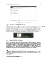
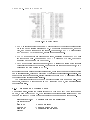
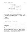
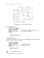
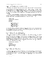
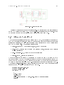
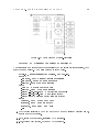
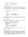
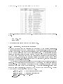
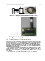
Figure 1.1: (a)MicroHOPE Block diagram.
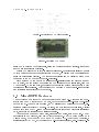
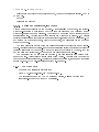
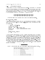
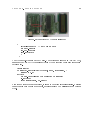
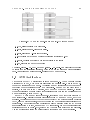
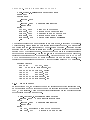
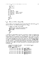
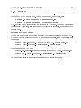
Figure 1.2: MicroHOPE board
learn how to program the peripherals, using the Special Function Registers, there is no
need to use these library functions.
MicroHOPE allows you to code in assembly language. This feature is included mainly
to get a better idea about the architechture of the uC, by playing with the registers and
assembly instructions directly. The content of registers can be displayed using LEDs
connected to the I/O ports of the micro-controller.
Since microHOPE comes with a bootloader pre-installed inside the program memory
of Atmega32, you can upload code using the USB interface with a single click, from the
GUI provided. At the same time, executing the compile and upload programs from a text
terminal are also explained. For compiling the C program we use the avr-gcc compiler
and avrdude for uploading it to the target.
1.1
MicroHOPE Hardware
A block diagram of microHOPE hardware is shown in gure 1.1. Programs can be uploaded from the PC through the USB port, with the help of the pre-loaded boot-loader
code on the uC. To load a new program, the PC asserts the RTS signal of MCP2200, generating a pulse that resets ATmega32. On reset, the boot loader code will start, waiting
for new code from the PC. If new code is available it is loaded and control is transferred
to it, otherwise the existing code will start running.
Atmega32 has 32 Input/Output pins, organized as 4 ports, each 8 bit wide. The IC
is available in DIP package, that can be socket mounted. The ATmega32 has 32 kB of
Flash memory, 512 bytes EEPROM and 2 kB Static RAM. Three Timer/Counters, a
serial interface (USART), a byte oriented Two-wire Serial Interface, an 8-channel 10-bit