1
LINkits Demonstration Application
In order to retain versatility in the selection of the MCUs used for the master and slave nodes, the boards
are available separately. There is also an accessory kit that includes a 500-mA power supply, an RS-232
cable, and a CD containing the documentation and software. This includes the application programs and
the LIN drivers for each node, allowing users to develop their own LIN applications using the LINkits
boards. The RS-232 cable is required to connect the LINkits board to a PC running the Metrowerks’
CodeWarrior® development environment. This cable is not part of the programmed demonstration
application.
Each slave has four LEDs whose states can be controlled by a single push-button switch. The resulting
four bits of data is returned to the master and displayed on four of its eight LEDS. The other four LEDs on
the master are used to indicate the slave type and ID. Two LEDs show the slave type (GR, EY, QY, or QL)
and the other two correspond to the four IDs allocated to that particular type. If more than one slave is
connected, the master’s display cycles round all those present on the bus. The sending of header frames
from the master can also be switched off to demonstrate the slaves’ ability to enter low-power sleep mode
in the absence of LIN activity (not applicable to the QY4 slave).
NOTE
With the exception of mask set errata documents, if any other Motorola
document contains information that conflicts with the information in the
device data sheet, the data sheet should be considered to have the most
current and correct data.
2
LINkits Demonstration Application
The master has two modes selected by its slide switch. In one mode, a single lit LED sweeps up and down
the display indicating that no LIN header frames are being sent. In this mode any slaves connected should
be in sleep mode.
With the switch in the other position, the master sends headers for all the IDs used in the demonstration
application and checks to see which are actually present. If a slave is present, the identification code and
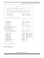
data is displayed in turn for all the IDs for which a response is received. The IDs used are shown in Table 1.
Table 1. The LIN IDs Used by Each Type of Slave
Slave
Default ID
Configurable IDs
Master LED ID Code
(d: default)
Alternative IDs
GR60
$29
$2A, $2B & $28
1101 (d), 1110, 1111 & 1100
$2C, $2D, $2E & $2F
EY16
$21
$22, $23 & $20
1001 (d), 1010, 1011 & 1000
$24, $25, $26 & $27
QY4
$19
$1A, $1B & $18
0101 (d), 0110, 0111 & 0100
$1C, $1D, $1E & $1F
QL4
$11
$12, $13 & $10
0001 (d), 0010, 0011 & 0000
$14, $15, $16 & $17
The master cycles round the IDs of all the slaves that it finds to be present and displays each slave’s ID
using the bottom (leftmost) four LEDs. The two leftmost LEDs show the slave type, and the next two
LEDs show the two LSBs of its ID using the code shown in Table 1.
LINkits LIN Evaluation Boards, Rev. 2
2
Freescale Semiconductor