1
G-Link®-LXRS® Wireless Accelerometer Node User Manual
6.
Sensor Settings and Operation
Sensor Settings and Operation
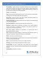
. The node configuration interface includes settings for measurement units and conversion values.
The G-Link®-LXRS® sensors are calibrated at the factory and require no user adjustment of the
conversion values. There are preset measurement units, as well as a user-defined field. Because
the wireless sensor system is digital, the analog voltage readings from the sensors are converted
into a digital equivalent value based on the volt-to-bit scale of the internal analog-to-digital voltage
converter (A/D converter). Sensor readings can be displayed and recorded in A/D value (bits)
directly or further converted to engineering units by applying conversion values and a conversion
formula. For more information see Conversion Values on page 39, and for instruction of adjusting
units see Measurement Units on page 38.
6.1
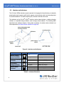
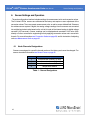
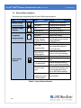
Node Channels Designations
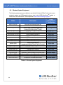
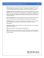
Sensors are assigned to a specific channel number at the factory and cannot be changed. For
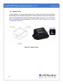
sensor orientation information see Sensor Frame on page 30.
Channel
Description
1
2
3
4
accelerometer channel 1 (x-axis)
accelerometer channel 2 (y-axis)
accelerometer channel 3 (z-axis)
temperature channel
Table 1 - Channel Designations
37