1
Installation
2.5.4
AC Conductor Wiring
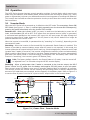
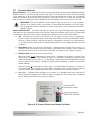
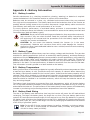
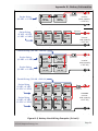
The following steps are basic guidelines for installing and connecting the AC wiring into and out
of the inverter. Refer to Section 2.5.5 and Figure 2-11 before beginning.
WARNING: Before making any AC connections, make sure the inverter is disconnected
from the battery and there is no other source of live power connected to the inverter.
Wiring the Inverter AC Input
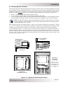
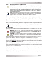
1. Remove the two Phillips screws on the AC Access Cover (see Figure 1-3, Item 15) to access
the internal AC Terminal Block (see Figure 2-10).
2. Route the cable from the AC electrical main panel through one of the strain relief clamps to
the AC INPUT. Tighten the strain relief clamp securely on the cable. Always leave a little extra
slack in the wiring.
3. Connect the LINE IN (brown) from the main panel’s dedicated breaker to the “HOT IN” terminal.
Tighten the “HOT IN” terminal to 16 in lbf (1.8 N-m).
4. Connect the NEUTRAL IN (blue) from the main panel’s neutral busbar to the “NEUT IN” terminal.
Tighten the “NEUT IN” terminal to 16 in lbf (1.8 N-m).
Wiring the Inverter AC Output
1. Route the cable from the inverter’s AC OUTPUT to the AC electrical sub-panel through the
strain relief clamps. Tighten the strain relief clamp securely on the cable.
2. Connect the LIVE OUT (brown) wire from the “HOT OUT” terminal to the sub-panel main breaker.
Tighten the “HOT OUT” terminal to 16 in lbf (1.8 N-m).
3. Connect the NEUTRAL OUT (blue) from the “NEUT OUT” terminal to the sub-panel’s neutral
busbar. Tighten the “NEUT OUT” terminal to 16 in lbf (1.8 N-m).
Wiring the Inverter AC Ground
1. Combine the ground (green w/yellow stripe) wire from the main panel’s ground busbar and the
ground (green w/yellow stripe) wire from the sub-panel’s ground busbar. After these grounds
are combined, connect them to the “AC GROUND” terminal. Tighten the “AC GROUND” terminal
to 16 in lbf (1.8 N-m).
AC Wiring Inspection
1. Verify all cable runs are secured. If installed in a mobile installation, use wire ties or other
non-conductive fasteners to prevent chafing or damage from movement and vibration.
2. Verify strain reliefs or grommets are in place to prevent damage to the wiring or conduit where
it passes through walls/bulkheads or other openings.
3. After verifying all AC connections are correct and all inverter AC terminal screws are torqued to
16 in lbf (1.8 N-m), replace the AC wiring access cover and the covers to the main electrical/
distribution panel.
2.5.5
AC Wiring Configuration
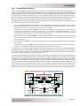
The wiring configuration for installing and connecting the AC conductors into and out of the inverters
(MS2712E & MS4124E models) requires an AC source1 of 230VAC @ < 30 amps. The maximum
input breaker required is 30A (single pole), and the minimum wire size is #10 AWG/5.3 mm2 (In
& Out). The maximum inverter pass-thru capacity is 3600W (30A @ 230VAC). Refer to the wiring
diagram in Figure 2-11.
Note 1: AC Source is from either the utility/grid power (i.e., shore power) or an AC generator.
© 2010 Magnum Energy, Inc.
Page 22