1
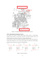
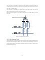
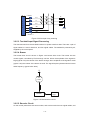
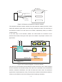
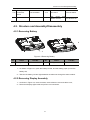
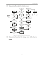
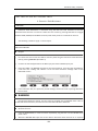
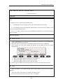
The 1.5V conversion circuit is used to convert +5V to 1.5V through a low-voltage difference
converter, and the voltage control is determined by peripheral sampling resistor in terms of
R1=R2*[ (VOUT/0.9)-1].
U24
VIN
V+
C+
GND
Vout
C-
Vout
R1
R2
Figure 3-15 1.5V conversion circuit
3.2.4.2. Description of Delay Line Circuit
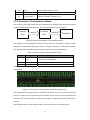
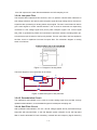
The delay line unit is used to integrate CW signals into one-way current signal through the
delay line; however, to accommodate the subsequent quadrature demodulation, filter,
amplifier and A/D converter, it needs to convert current signal to voltage signal output.
Therefore this unit consists of two parts, delay line circuit and I-V conversion circuit.
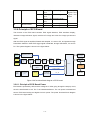
3.2.4.3. Description of Pencil Probe Unit
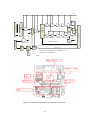
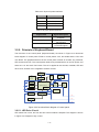
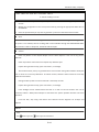
The pencil probe unit consists of transmission and reception circuits.
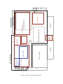
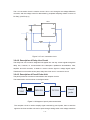
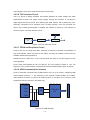
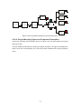
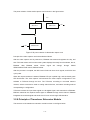
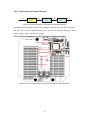
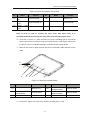
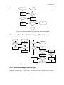
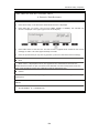
The transmission circuit is shown in the figure below:
PHV
CW
CON2
MD1201
TC2320
Pencil
probe
Figure 3-16 Diagram of pencil probe transmission
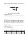
The reception circuit is used to amplify signal received by pencil probe, then to send the
signal to the front-end filter unit and to pass through analog switch with voltage waveform
3-35