1
2701-900-01.book Page 14 Wednesday, August 3, 2011 9:43 AM
8-14
Triggering
Model 2701 User’s Manual
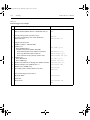
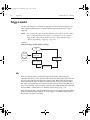
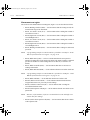
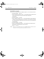
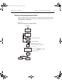
D.
E & F.
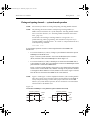
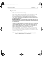
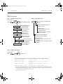
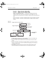
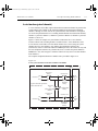
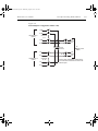
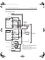
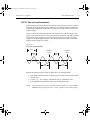
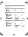
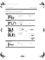
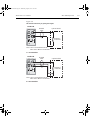
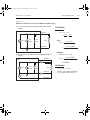
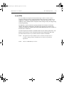
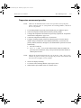
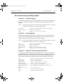
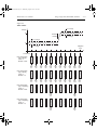
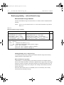
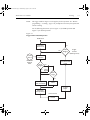
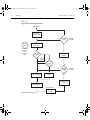
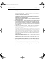
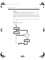
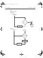
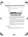
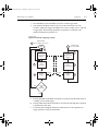
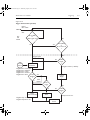
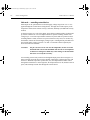
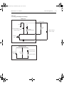
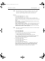
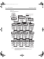
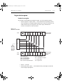
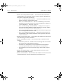
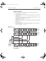
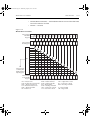
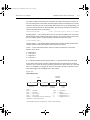
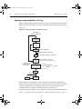
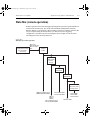
After the relay settles, the Model 7002 outputs a Channel Ready pulse. Since the
instrument is programmed to scan 400 channels, operation loops back up to point
B, where it waits for an input trigger.
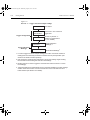
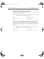
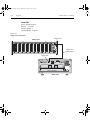
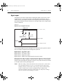
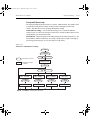
Model 2701 operation is at point A waiting for a trigger. The output Channel
Ready pulse from the Model 7002 triggers the Model 2701 to measure DUT #1
(point E). After the measurement is complete, the Model 2701 outputs a completion pulse (point F) and then loops back to point A where it waits for another input
trigger.
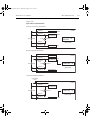
The trigger applied to the Model 7002 from the Model 2701 closes the next channel in the
scan. This triggers the Model 2701 to measure the next DUT. The process continues until
all 400 channels are scanned, measured, and stored in the buffer.
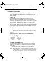
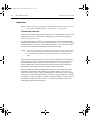
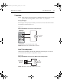
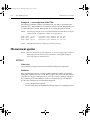
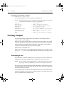
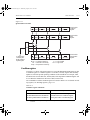
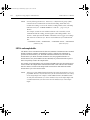
External triggering with BNC connections
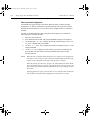
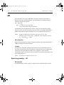
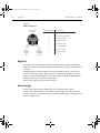
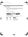
An adapter cable is available to connect the micro-DIN Trigger Link of the Model 2701 to
instruments with BNC trigger connections. The Model 8503 DIN to BNC Trigger Cable
has a micro-DIN connector at one end and two BNC connectors at the other end. The BNC
cables are labeled VMC (trigger line 1) and EXT TRIG (trigger line 2).
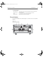
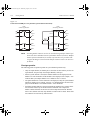
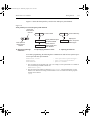
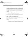
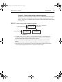
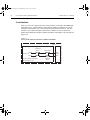
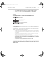
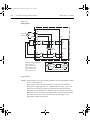
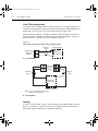
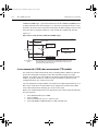
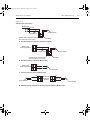
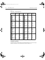
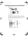
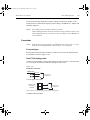
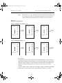
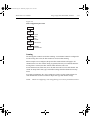
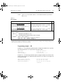
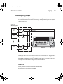
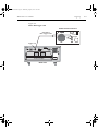
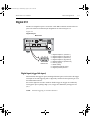
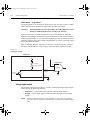
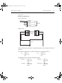
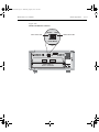
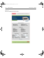
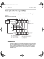
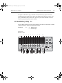
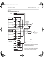
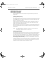
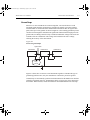
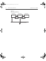
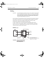
Figure 8-9 shows how a Keithley Model 220 Current Source can be connected to the
Trigger Link of the Model 2701 using the adapter cable. When used with the STEP mode
of the Model 220, you can perform synchronized source-measure operations without the
use of a computer. Whenever the Model 220 receives a trigger from the Model 2701, it
will step to the next current source value.