1
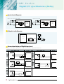
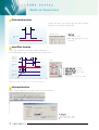
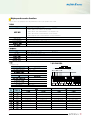
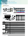
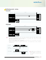
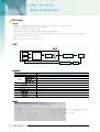
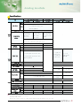
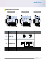
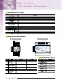
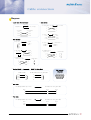
Names of parts and functions
G7F-AD2A
④
G7F-DA2I
G7F-DA2V
④
③
①
①
24V 24G
24V 24G
Input
Input
G7F- AD2A
PR OG RAMM EABL
LOGIC
CONTROLLER
⑤
Input
select
Ch3
Ch2
Ch1
Ch0
⑤
⑥
⑤
PWR
Ch0
Ch1
Ch2
Ch3
V0 COM0 V1 Com1 V2 Com2 V3 Com3
I0 · I1 · I2 · I3
24V
24V
I-
24G
I-
I-
I-
V0+ V1+ V2+ V3+
V0- V1- V2- V3-
·
②
②
Name
G7F-AD2A
PWR LED
⑥
G7F-DA2V
PROGRAMMABLE
LOGIC
CO NTRO LLER
PWR
Ch0 Ch1 Ch2 Ch3
I+ I+ I+ I+
②
No.
①
⑥
G7F-DA2I
PROGRAMM EABL
LOGIC
CONTROLLER
PWR
③
①
G7F-DA2I/G7F-DA2V
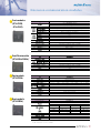
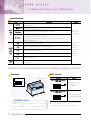
Indicate the operating status.
Analog input terminal.
Voltage
input
②
Analog input terminal
Current
input
Ch0
V0 Com0
·
I0
Ch0
V0 Com0
·
I0
∙When current input is used, short the V and I terminal
Jumper pin of analog input (V/I).
Voltage input
Input
select
③
Ch 3
Ch 2
Ch 1
ChO
Jumper pin of analog input
V
Current input
Ch 3
Ch 2
Ch 1
ChO
I
Connect left parts by
jumper pin
④
External power input terminal
⑤
Extension cable
⑥
Extension cable connector
Ch 3
Ch 2
Ch 1
ChO
Connect right parts
by jumper pin
External voltage 24VDC needs to this terminal.
The cable is used to connect while an analog mixture module is used.
The connector connects extension cable when an extension module is used.
21