1
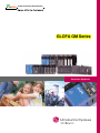
GLOFA GM Series
Programmable Logic Controller
Table of contents
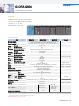
GLOFA-GM7 I 9
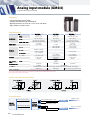
Analog input module (GM4/6) I 44
GLOFA-GM7U I 11
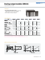
Analog output module (GM4/6) I 45
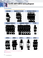
GLOFA-GM7/GM7U wiring diagram I 14
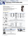
Temperature control module (GM4) I 46
GLOFA-GM7/GM7U expansion unit I 16
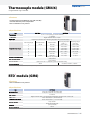
Thermocouple module (GM4/6) I 47
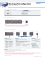
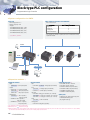
Block type PLC configuration I 19
RTD module (GM4) I 47
GLOFA-GM6 I 21
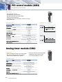
PID control module (GM4) I 48
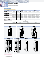
GLOFA-GM4 I 25
Analog timer module (GM4) I 48
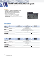
GLOFA-GM Fast Enet (Ethernet) system I 32
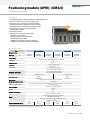
Positioning module (APM): (GM4/6) I 49
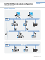
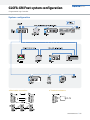
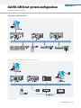
GLOFA-GM Ethernet system configuration I 33
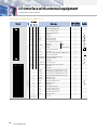
I/O interface with external equipment I 50
GLOFA-GM Fnet (Fieldbus) system I 34
Example of connection with drivers I 52
GLOFA-GM Fnet system configuration I 35
High speed counter module (GM4/6) I 53
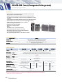
GLOFA-GM Cnet (Computer link) system I 36
GLOFA-GM program S/W (GMWIN) I 54
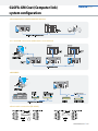
GLOFA-GM Cnet (Computer link) system configuration I 37
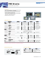
PMU 30 series I 55
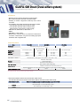
GLOFA-GM Dnet (DeviceNet) system I 38
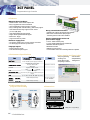
XGT PANEL I 56
GLOFA-GM Dnet system configuration I 39
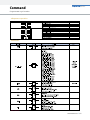
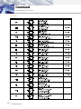
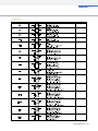
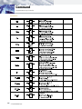
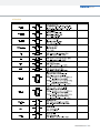
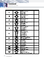
Command I 57
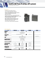
GLOFA-GM Pnet (Profibus-DP) system I 40
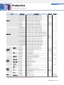
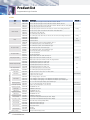
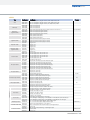
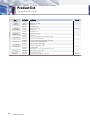
Product list I 63
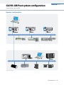
GLOFA-GM Pnet system configuration I 41
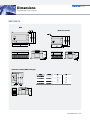
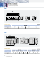
Dimensions I 67
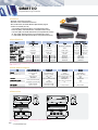
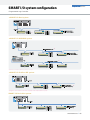
SMART I/O I 42
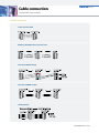
Cable connection I 69
SMART I/O system configuration I 43
GLOFA-GM Series
I3