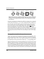
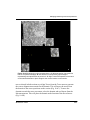
1
Quick Start
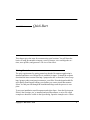
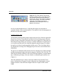
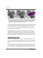
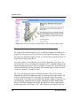
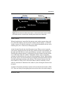
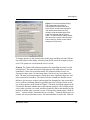
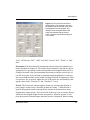
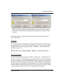
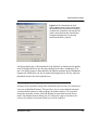
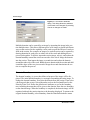
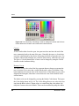
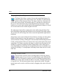
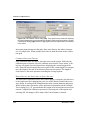
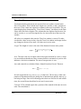
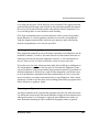
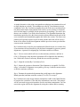
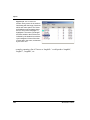
Figure 1.2. The Tools window. This window
should be visible at the top of the Reconstruct
main window. Use the left mouse button to
select a tool. The Line Tool used for calibration
lines is the 8th button. The Pencil Tool is the
10th button. The Wildfire tool button is
depressed and so a description of the tool
appears in the title bar.
tion by section through the series. Verify that the images were imported as
expected with the correct section numbers. The number of each section appears in
the title bar of the main window.
CALIBRATE PIXEL SIZE
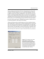
An important parameter during image import is the pixel size, which we ignored in
the previous section. This parameter specifies the size of image picture elements
(pixels) in terms of the units of measure of the series (Chapter 9). If the pixel size
in the Import Images dialog was accurate, no further calibration is required. However in most cases the pixel size should be adjusted using the image of a calibration grid or scale that was photographed with the series. This is best done before
any alignments or tracing, since changing the pixel size later can invalidate these
adjustments.
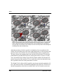
The process of calibration in Reconstruct involves drawing traces of known length
and then entering that length value into the program. Select the Line Tool (Fig. 1.2)
from the tools window and draw a line trace of known length on a section containing a calibration grid image. (For more details on calibration grids and lines see
Chapter 9.)
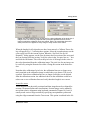
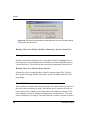
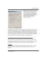
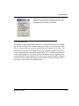
After the calibration trace is drawn, select the Calibrate item from the Traces
menu. A dialog box will appear for each calibration trace displaying the current
length of the trace. Enter the actual length of the trace in place of the current
length.
4
Reconstruct v1.0.6.1