1
Page 2
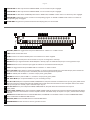
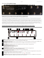
9 STATUS LED The LED only be active in DIRECT MODE, it turns on when loop 8 is engaged.
10 STATUS LED The LED only be active in DIRECT MODE, it turns on when loop 9 is engaged.
11 STATUS LED The LED shows TUNER ON/OFF status in PGM mode, in DIRECT mode it will turn on when loop 10 is engaged.
LED In PGM mode it turns on when its corresponding program is recalled. In DIRECT mode it will turn on when its
12 STATUS
corresponding loop is engaged.
13 GUARD BAR The guard bar protects the buttons and display panel, it is remove-able.
Rear Panel
15
15
16
16
17
17
11
12
13
8
14
11 12 13 14
8
11 22 33 44 55 66 77 88 99
10
10
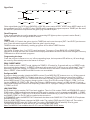
1 MIDI OUT/THRU The toggle switch setups the MIDI JACK for “OUTPUT” or “THRU” function.
2
3
4
5
6
(1) MIDI OUT/THRU
LINK Connect the link cable here.
The toggle switch setups the MIDI JACK for “OUTPUT” or “THRU” function.
9V IN Connect to an external 9V DC power source 5.5x2.1mm center negative.
(2) LINK
BUF IN Signal inputConnect
via this jack
fedcable
to a buffer
the islink
here.circuit prior to being sent to the loops.
BUF OUT The input
(3) signal
9V INreceived at the BUF-IN jack is directly output via the BUF OUT jack prior to being send to loops.
to an
9Vvia
DCbuffered
power source,
5.5x2.1mm,
negative
TUNER When OUTConnect
are muted,
theexternal
input signal
or non-buffered
reaches
this jack.center type.
(4)switch
BUF setups
IN
the MIDI JACK for “OUTPUT” or “THRU” function.
7 INPUT The toggle
Signaljacks
inputforviaseries
this jack
fed to a7),
buffer
circuit
prior
being sent
to the loops.
and OUT2 Output
loopsis(LOOP1the input
signal
viatobuffered
or non-buffered
Input jacks reaches the
8 OUT1
two jacks via the 7 series loops, OUT-1 and OUT-2 jacks are Internally connected in parallel.
9
10
11
12
13
14
15
16
17
(5) BUF OUT
SEND 1–7 Send jacks of LOOP1–7, connect to input jack of guitar pedals.
The input signal received at the BUF-IN jack is directly output via the BUF OUT jack
RETURN 1–7 Return
jacks
of LOOP1–7,
prior
to being
send toconnect
loops. to output jack of guitar pedals.
IN8 - IN9 - IN10(6)
Input
of separate LOOP8–10. prior to sending to loops.
TUNER
When
OUT
are muted,
the
input signal via
or non-bufferd
reaches
this jack
S8 - S9 - S10 SEND
jack of
separate
LOOP8,
LOOP9,LOOP10,
thebuffered
jacks should
be connected
to the input
of guitar pedals. These
jacks also function as latching N.C (Normally Closed) switch which works as foot-switch to control amplifier channel. The sleeve
and tip of the jack
“closed”/“open” when the loop is “off/on”.
(7)are
INPUT
R8 - R9 - R10 Return
of separate
LOOP8,the
LOOP9,LOOP10,
the“OUTPUT”
jacks shouldorbe
connected
to the output of
Thejack
toggle
switch setups
MIDI JACK for
“THRU”
function.
guitar pedals.
(8) OUT1
andjack
OUT2
OUT8 - OUT9 - OUT10
Output
of separate LOOP8, LOOP9, LOOP10, the jacks also function as latching N.O (Normally Open)
switches which work
as
foot-switch
to
control
amplifier
channel.
tip of
jack areor
“open”/“closed”
Output
jacks
for
series
loops
(LOOP1
~ 7),The
thesleeve
input and
signal
viathe
buffered
non-bufferd when the loop
is off/on.
jacks
reaches
the two
jacks
viathe
theMIDI
7 series
OUT-1
and OUT-2
are
MIDI IN Receives Input
MIDI data
from
an external
MIDI
device,
IN is loops,
not available
in when
it is set jacks
as DOWNLOAD
SLAVE
device. Check detail
in MIDI and
LINK sections.
Internally
connected
in parallel.
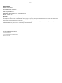
MIDI OUT/THRU Transmits MIDI data to an external MIDI device.
(9) SEND 1~7
GROUND STUB Connect the stub to earth to ground the frame.
Send jacks of LOOP1~7, connect to input jack of guitar pedals.
(10) RETURN 1~7
Return jacks of LOOP1~7, connect to output jack of guitar pedals.
(11) IN8,IN9,IN10
Input of separate LOOP8~10. prior to sending to loops.