1
11/20/09
9:21 AM
Page 5
SECTION 3: Installation and Setup
5
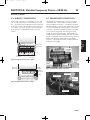
3.1 GENERAL INSTALLATION
GUIDELINES
The grounding should extend to the water-bearing layer to
be effective.
• In order to avoid abrasion to the power and control
cables, pad the top of the well casing (a rubber pad is
recommended) where the cable will pass over it; use a
cable reel for cable control.
If a metal drop pipe is used, then ground to the drop pipe.
• The unit must always be easy to rotate in the hoisting
gear.
• Lay power and control cables out straight on the
ground (no loops) before installation. Guide cables
during lowering so that they are not stretched or
squeezed while pump is being installed. Make sure
that cable insulation is not nicked or damaged before
or during installation. Never use the electrical cables to
move the motor/pump.
• The pump and motor are heavy. Make sure that all
connections are secure and that the hoisting gear is
adequate to do the job before starting to lift pump.
Don’t stand under the unit. Don’t allow extra people
into the area while hoisting the unit.
• If motor or pump/motor unit are attached to a
supporting girder, do not remove girder until unit is
vertical.
• Install pump at least 10’ (3m) below the lowest water
level during pumping, but at least 6’ (2m) above the
bottom of the well.
• 6" motors must be installed in a vertical position only.
• 4" motors can be operated in vertical or horizontal
positions. Note that the thrust bearing will have shorter
life in a non-vertical application. In such an
installation, keep frequency of starts to less than 10 per
day.
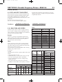
3.2 PROPER GROUNDING
Hazardous voltage. Can shock, burn or
cause death. Installation or service to electrical equipment
should only be done by qualified electrician.
Control panels must be connected to supply ground
Proper grounding serves two main purposes:
1. It provides a path to ground in case of a ground-fault.
Otherwise the current would present a shock or
electrocution hazard.
2. It protects equipment from electrical surges.
Use wire the same size as, or larger than motor’s currentcarrying wires (consult Tables in the motor section).
Installations must comply with the National Electric Code
as well as state and local codes.
Ground to casing if it is metal, and extends within 20’ of
motor.
Do not ground only to the supply ground or driven
grounding rod. These will not protect the pump.
All motors are internally grounded and requires a 3 or
4-wire drop cable.
3.3 CORROSIVE WATER AND
GROUND
Some waters are corrosive, and can eventually corrode the
ground wire. If the installation uses a metal well casing,
any ground current will flow through it. In the case of
plastic piping and casing, the water column would carry
the current in a ground fault situation.
To prevent this, route the motor ground wire and the motor
power leads through a GFCI with a 10 mA set point. In this
way, the GFCI will trip when a ground fault has occurred
AND the motor ground wire is no longer functional.
3.4 CHECK VALVES
Check valve installation is necessary for proper pump
operation. The pump should have a check valve on its
discharge, or within 25 feet (7.62 m) of the pump. For
very deep wells, locate a check valve at least every 200
feet (61 m).
• Use only spring type or gravity-poppet check valves.
Swing type valves can cause water hammer problems.
• Do not use drain-back style check valves (drilled).
Check valves serve the following purposes:
• Maintain Pressure: Without a check valve, the pump
has to start each cycle at zero head, and fill the drop
pipe. This creates upthrust in the motor, and would
eventually damage both the pump and motor.
• Prevent Water Hammer: If two check valves are used,
and the lower one leaks, then a partial vacuum forms
in the pipe. When the pump next starts, the flow fills
the void area quickly, and creates a shock wave that
can break piping and damage the pump. If you get
water hammer on pump start, this may be the cause.
• Prevent Back-Spin: Without a functioning check valve,
upon shutoff, the water drains back through the pump,
and cause it to rotate backwards. This can create
excessive wear on the thrust bearing, and if the pump
restarts as water is flowing down the pipe, it will put an
excessive load on the system.
All systems must have lightning (surge) protection with a
secure connection to ground.
PN793
Installation
and Setup
PN793