1
Chapter 2 Running the Simulator
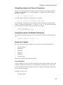
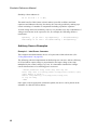
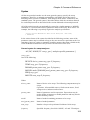
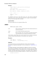
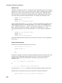
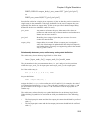
Example with .PRINT and node called V+
.PRINT TRAN {Vec('V+')}
A similar syntax is required when using the front end plotting commands.
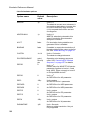
Device Pin Currents
Device pin currents are named in the following form:
device_name#pin_name
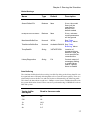
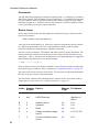
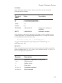
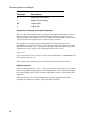
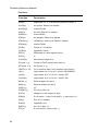
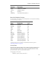
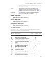
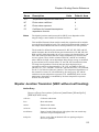
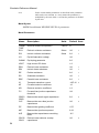
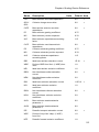
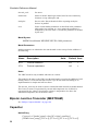
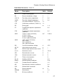
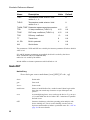
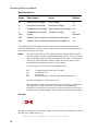
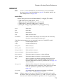
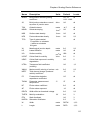
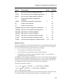
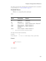
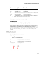
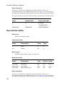
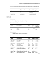
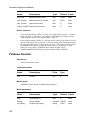
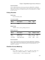
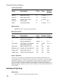
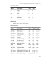
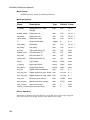
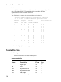
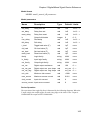
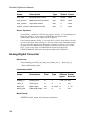
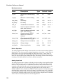
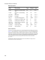
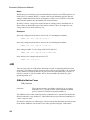
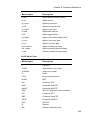
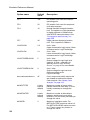
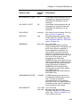
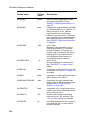
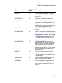
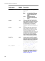
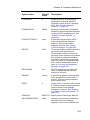
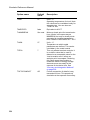
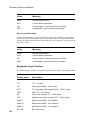
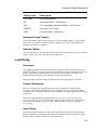
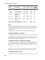
For primitive devices (i.e. not sub-circuits) pin_name must comply with the table on
page 20. For example the current into the collector of Q23 would be Q23#c.
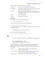
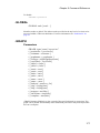
The pin names for sub-circuits depend on whether the pinnames: specifier (see
“Subcircuit Instance” on page 94) is included in the netlist entry for the device. If it is
the pin current name will be the name listed after pinnames:. If it isn't then they are
numbered in sequence starting from 1. The order is the same as the order they appear
in the netlist device line. For example, if the subcircuit line is:
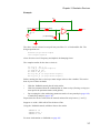
X$U10 N1 N2 N3 N4 N5 LM324 pinnames: VINP VINN VP VN VOUT
The current into the last pin (connected to N5) would be U10#VOUT
(Note that 'X$' is stripped off as explained above - page 20).
If the netlist line is:
X$U10 N1 N2 N3 N4 N5 LM324
The same current would be U10#5
Internal Node Voltages
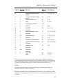
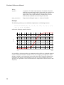
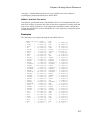
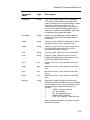
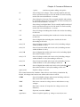
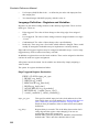
Some devices have internal nodes and the voltages on these are output by the
simulator. These are named in a similar manner to pin currents i.e.
device_name#internal_node_name
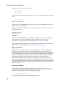
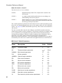
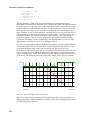
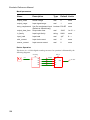
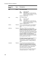
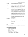
The internal_node_name depends on the device. For example, bipolar transistors
create an internal node for each terminal that specifies a corresponding resistance
parameter. So if the RE parameter is specified an internal node will be created called
emitter.
25