1
EUROSTER 1100M – USER MANUAL
2
b. mounting of the sensor:
● the sensor is NOT intended for immersion in liquids and installation on flues
between the boiler and chimney
● install the sensor on a bare return pipe (as close to the boiler as possible)
● secure the sensor on the pipe by tightening the supplied buckle clip.
NOTE: As a recommendation, the inlet pipe should be provided with thermal insulation on
the section between the boiler and the temperature sensor. If the central heating system is
supplied by both a coal- and a gas-fired boiler, the temperature sensor should be installed at
the meeting point of the two outlet pipes and insulated.
c. connecting of the power supply cable to the valve:
● connect the black wire (valve opening) to terminal (L)
● connect the blue wire (common) to terminal (N)
● connect the brown wire (valve closing) to terminal (L)
d. check-up of connections:
● make sure that the wires have been connected as indicated
e. connection of the controller:
● upon securing the cables against accidental pullout, connect the power supply
cable to a 230V/50Hz grounding socket.
NOTE: At the mounting location of the controller ambient temperature should not exceed
40ºC.
3.
OPERATION
a. start up:
● set the left-hand switch (~) to position I,
● upon energising all the segments of the display light up for 2 seconds,
● the current temperature measured by the sensor is displayed and the controller
operates according to the factory preset values (temperature of system water: 40°C,
hysteresis: ± 1°C, neutral response speed: 16).
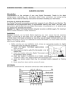
b. description of display functions
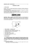
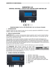
● display continuously on – current temperature measured by the sensor,
● blinking display – setpoints of: temperature, hysteresis, response speed,
● red LED on (the upper one) – mixing valve status indication – opening movement
● green LED on (the lower one) – mixing valve status indication – closing movement
c. setting the temperature and hysteresis
● for viewing the temperature setpoint press the right- or left-hand switch under the
display – the figures will start blinking indicating that the current temperature
setpoint is being displayed,
● use the right-hand or left-hand switches to increase or decrease the displayed
temperature within the adjustment range 10°C – 80°C,
● after ca. 4 sec. the display will stop blinking indicating that the preset temperature
has been stored. The display will return to displaying the current temperature (as
measured by the sensor).