1
EVS Broadcast Equipment S.A.
Issue 1.1.A - October 2014
Procedure
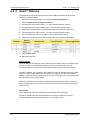
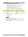
To configure the jumpers inside the DC-100:
1. Power down the DC-100.
2. Using a Phillips screwdriver, remove the top cover from the DC-100.
To do so, you will need to remove 3 screws from each side of the unit:
o
2 from the rear
o
1 from the center of the front of the unit
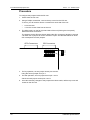
3. The GPIO card is on the far right hand side of the unit (if facing the front panel),
behind the GPIO connectors.
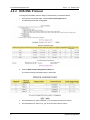
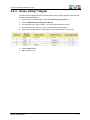
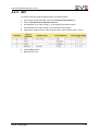
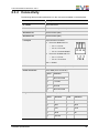
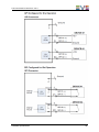
The jumpers for the GPIs are directly behind the GPI connectors, labeled J7 through
J38. Each set of jumpers for a GPI consists of 4 pins. See the table below for which
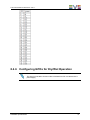
GPI corresponds to which jumpers.
GPO Connectors
GPI Connectors
J7
J22
Pin 4
Pin 3
Pin 2
Pin 1
J23
J38
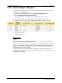
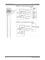
4. For Dry operation, set one jumper across pins 2 and 3.
Hang the second jumper off of pin 1.
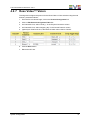
5. For Wet operation, set one jumper across pin 1 and 2.
Set the second jumper across pins 3 and 4.
6. Once all necessary changes to the jumpers have been made, refit the top cover and
screws on the DC-100.
30
Hardware Specifications