1
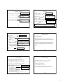
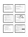
pmeas.va, delta_probe.def
•
‘power_dly.sp’ File
pmeas.va is a Verilog-A model that implements a power
supply that reports average power usage
– Included by power_dly.sp which is the top level Spice file
•
delta_probe.def is a Spectre HDL model that implements
a probe for measuring delay between two events
//pwr=subckts saves power for subcircuts
opts options pwr=subckts save=allpub
aliasGnd (gnd 0 ) vsource type=dc dc=0
– Included by power_dly.sp which is the top level Spice file
– Provided in the sample Analog HDL model library in the Cadence
distribution
– A very flexible model, look at the source code for more
documentation or Appendix D in the Verilog-A language reference
guide. Very similar in capability to the HSPICE ‘.measure’
statement if you are used to that.
BR 8/02
Global nodes, can be used in
subcircuits without passing them
on parameter list.
simulator lang=spectre
global 0 gnd vdd
Save power info for all
subcircuits,
Vsupply for ground.
//include "ami06.m"
Include files for different
technologies
//include "tsmc025.m"
include "tsmc018.m"
include "def.m"
Defines ‘N_def’, ‘P_def’ default
devices based on ‘N’, ‘P’ models
from included tech file.
7
BR 8/02
Parameter Definitions
8
Subcircuit Definitions
Using lmin, wmin so
// lmin, wmin defined in model file
can experiment with
subckt NAND2X1 A B Y vddc gndc
M3 (Y A net29 gndc) N_def w=2*wmin l=lmin different technologies.
M4 (net29 B gndc gndc) N_def w=2*wmin l=lmin
M2 (Y B vddc vddc) P_def w=2*wmin l=lmin
M1 (Y A vddc vddc) P_def w=2*wmin l=lmin
ends NAND2X1
parameters vdd_core=3.3 vss_core=0.0
parameters tr=.1n tf=.1n
parameters cload=15f
parameters pdelta=0.05n
parameters clkper=4n
parameters
subckt INVX1 A Y vddc gndc
M2 (Y A gndc gndc) N_def w=wmin l=lmin
M1 (Y A vddc vddc) P_def w=2*wmin l=lmin
ends INVX1
pwrstop=10*clkper
Should use parameter definitions for constant values – makes it
easier to experiment with different values.
subckt INVX4 A Y vddc gndc
M2 (Y A gndc gndc) N_def w=wmin*4 l=lmin
M1 (Y A vddc vddc) P_def w=2*wmin*4 l=lmin
ends INVX4
Using N_def, P_def so
that default values for
AS, AD, PS, PD are
calculated from W,L.
Passing in nodes for Vdd, Gnd so that power
supplies can be kept separate for power tracking.
BR 8/02
9
Sources, Circuit Instantiation
BR 8/02
10
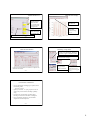
Power, Delay Measurement
Default power supply
v_vdd (vdd gnd) vsource type=dc dc=vdd_core
ahdl_include "pmeas.va"
Verilog-A model for power supply
model
Pmtr (vdd_dut) pmeas vsrc=vdd_core deltatime=pdelta period=clkper
vpulse1 (a gnd) vsource type=pulse val0=vss_core
val1=vdd_core period=clkper rise=tr fall=tf width=clkper/2
Instantiate power supply,will report avg pwr used.
// delay measurement
Clock source for
input node.
ahdl_include "delta_probe.def"
Driver (a a_out vdd gnd) INVX1
dut_tplh (a_out 0 nand2_out 0) delta_probe start_val=0.7*vdd_core \
Dut (a_out vdd nand2_out vdd_dut gnd) NAND2X1
start_mode=fall stop_val=0.3*vdd_core stop_mode=rise
Load (nand2_out nand2_out1 vdd gnd) INVX4
dut_tphl (a_out 0 nand2_out 0) delta_probe start_val=0.3*vdd_core \
start_mode=rise stop_val=0.7*vdd_core stop_mode=fall
‘delta_probe’ model used to measure delay between two
events. Instantiate two probes to measure tplh, tphl of DUT
(input ‘a_out’ to output ‘nand2_out’).
Instantiate driver, dut, and load cells. Note that dut has a
separate power supply (defined later in file).
BR 8/02
11
BR 8/02
12
2