1
Chapter 1
Cisco AS5850 Product Overview
Field-Replaceable Units
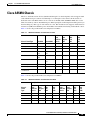
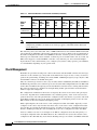
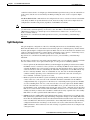
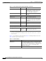
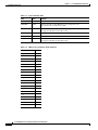
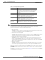
Table 1-12 DC-input Power Supply Circuits
Note
Circuit
Description
Circuit breaker
PEMF output is enabled when this pin is shorted to the —51V
monitor pin by way of the backplane. If the connection is broken,
the breaker is tripped and cannot be reset until the PEMF is
reinstalled.
Reverse polarity
An electronic interlock that provides reverse polarity protection.
Current monitor
Analog output voltage is proportional to DC-output current from
the PEMF to the backplane, as follows: 1A of current is
equivalent to 100 mV at the current monitor pin.
Voltage monitor
Analog output voltage is proportional to DC-output current from
the PEMF to the backplane, as follows: 1A of current is
equivalent to 100 mV at the voltage monitor pin.
Bell alarm
A terminal block for connecting to central office alarms (C, NC,
NO).
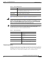
Connect the alarm port only to a safety extra-low voltage (SELV) source using 22 AWG, or thicker, copper
wire. SELV ratings are maximum 30 Volts AC (RMS), maximum 60 Volts DC, and maximum
50 VA power. The alarm port is rated for 2.0 Amp maximum current.
•
Bell alarm signaling
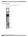
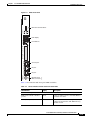
The PEMFs provide relay outputs for standard central office bell alarms. These bell alarm contacts
are available on a terminal plug mounted on the PEMF front panel.
•
Online insertion and removal (OIR)
The PEMFs support OIR, which means that you can remove or replace a PEMF while the system is
operating; system operation is not affected. Only qualified personnel should OIR a PEMF.
•
DC-input power filtering and power distribution
The PEMF first receives –48 VDC power using analog isolation circuits. The DC power passes
through a broadband EMI filter, then passes to a DC-to-DC converter on the RSC, where it is
converted and then routed back to the backplane for distribution to the other cards. A single PEMF
supports a fully configured chassis.
•
Maintenance monitoring
The PEMF contains the environmental maintenance bus (Mbus) module with a logic card, which
carries monitor signals throughout the chassis by way of two 10-pin molex MiniFit connectors.
There are no connectors accessible from the front of the PEMF; however, a DB-9 connector at the base
of the PEMF (visible only from below the chassis) connects a monitor cable to an optional AC-input
power shelf.
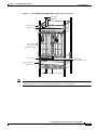
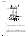
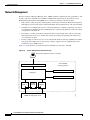
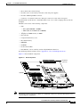
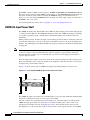
The PEMFs are located on the rear of the universal gateway. Figure 1-2 shows the location of the PEMFs
as viewed from the rear of the chassis.
Cisco AS5850 Universal Gateway Hardware Installation Guide
78-10573-06 0A
1-25