1
CT Corsair
Final Report
May 2, 2014
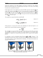
(Equation 1)
The spring force is defined as:
(Equation 2a)
Where k represents the spring constant in N/m and y is the linear displacement of one side of the
spring. This equation, becomes Equation 2b due to the shared spring force between the three
arms.
(Equation 2b)
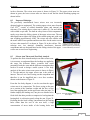
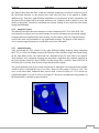
The free body diagram reveals the relation between the angle Φ, and the displacement of the
simulator in the y-direction. This relation is expressed in:
(Equation 3)
After substituting Equation 2b and Equation 3 into Equation 1 the following equation is
obtained.
(Equation 4)
With the relation between spring constant and platform force derived, an experiment was
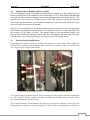
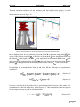
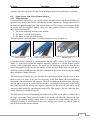
conducted to determine the spring constant. An angle finder was place on top of the platform in
line with the pivot point and pushrod location. The angle finder has a tolerance of 0.5o, and as a
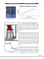
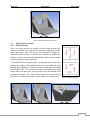
result the experiment is limited by this accuracy. A chain was attached to the platform at the
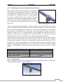
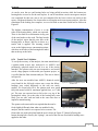
pushrod location and weights ranging from 5 to 320 lbs were hung off of the edge (depicted in
Figure 12). The weights represented varying amounts of pulling force that a pushrod could
exhibit on the platform. The weights have been calibrated by a certified metrologist to ensure the
weights were accurate within ±.001 lbs.
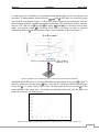
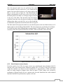
Each weight and corresponding displacement was recorded and plotted to verify that the spring
constant is a linear relationship. The spring constant was found to be 189000 N/m. As seen in
Figure 14, the weights between 110 to 320 pounds were used in the derivation due to
measurement tool limitations. The range of weights between 5 to 105 pounds did not result in a
noticeable displacement due to the large spring constant size. Raw data from the experiment can
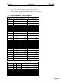
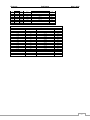
be found in Table 1-1 of Appendix 3: Supplementary Analysis Data.
15