1
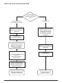
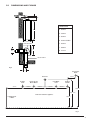
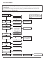
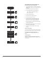
15.0 FAULT FINDING
E
F
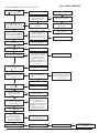
Check and correct if necessary
1. Electrical and pressure tube connections
2. Blockage of pressure tubes
3. Restriction in flue
4. Venturi
Gas at burner
NO
NO
Replace air
pressure switch
Ensure gas is on and purged
PCB - M4 connector is approx 230V AC,
terminals 36 & 38
YES
Replace gas valve
NO
neon illuminated
YES
Turn selector switch to
‘Reset’ position
NO
Replace PCB
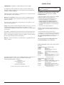
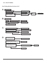
G
1.
2.
Check the burner setting pressure of
the gas valve
(see Section 9.2 of Commissioning)
Voltage at modulating coil of gas valve is:
Max. burner press.approx 9V DC (13V DC LPG)
Min. burner press.approx 1V DC
Current at modulating coil of gas valve is:
(Use an instrument with average function for this
measure)
30 ÷ 230 mA DC (45 ÷ 310 mA DC LPG)
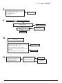
H
44
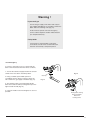
Check and correct if necessary
1. Ignition electrode and lead
2. Electrode connection
3. Spark gap and position
YES
NO
Replace gas valve
Replace PCB
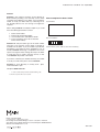
NO
YES
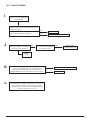
230V at Main PCB - M4
connector across terminals
37 & 38. Check wiring
YES
Replace PCB
Replace gas valve
electrical
plug/igniter assy