1
Chapter 5: ARGUS
5.1 ARGUS movement detector, surface-mounted
INSTABUS ARGUS 220 Connect
Art. no. 6315 ..
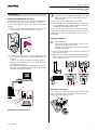
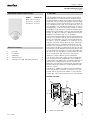
2. Installation
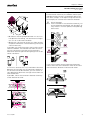
B
Top section
C
Cover plate
D
Sensor head
E
Contact pins
Correct
F
Cable entry for bus line from underneath
Not optimum
G
Cable entry for bus line from behind
Incorrect
H
Terminal block for connecting the bus line and for
locating the contact pins
Explanation of the symbols used
What you need to know about the installation site
¼
Danger due to electrical current!
All work on the device should only be carried
out by qualified electricians. Both the countryspecific regulations and the valid EIB guidelines
should be observed.
A
B
G
F
C
D
E
When selecting a suitable installation site, you should
take numerous standpoints into account so that the
movement detector operates at the optimum level.
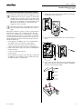
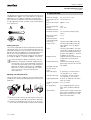
The following diagram shows the ranges of the ARGUS. They are based on average temperature conditions at a mounting height of 2.5 m. The range of a
movement detector can fluctuate considerably at variable temperatures.
m
A
Sensitivity controller
B
Time controller
C
Brightness controller
D
Functional display, lights up each time movement is detected
14
E
Brightness sensor
10
F
Programming area for magnet
8
G
Programming LED
6
2,5m
0
0,8m
0
4
12
2
4
6
8
B
A
10 12 14 16m
C
4
2
0
2
4
6
8
10
12
14
4
2
0
2
4
6
8
10 12 14 16m
– A: Inner security zone with an angle of detection of
360° and a radius of approx. 4 m.
– B: Central security zone with an angle of detection
of 220° and an area of detection of approx.
9 m x 18 m.
– C: Outer security zone with an angle of detection of
220° and an area of detection of approx.
16 m x 28 m.
Version 03/04
2