1
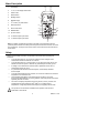
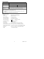
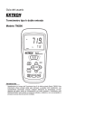
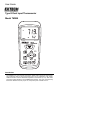
Meter Description
12
1.
LCD display
2.
T1, T2, T1-T2 display select button
3.
Power button
4.
SETUP button
5.
Backlight button
6.
Min/Max button
7.
o
8.
Data Hold button
9.
Down arrow button
o
13
1
o
C F Kelvin ( K) select button
2
10. ENTER button
11. Up arrow button
12. T2 Thermocouple input socket
3
4
5
11
10
9
6
8
13. T1 Thermocouple input socket
7
Note: The battery compartment is located on the back of the instrument under the
protective jacket. Remove the rubber protective jacket that encases the meter to access
the compartment. The tripod mount access is also on the back of the instrument above
the tilt stand.
Safety
Please read the safety information and operation instructions before operating this
instrument.
•
To avoid electrical shock, do not use this instrument when voltages at the
measurement surface exceed 24V ac or 60V dc.
•
To avoid electrical shock or personal injury, do not apply more than 20V ac rms,
between the thermocouples, or between any thermocouple and earth ground.
•
If voltage on the measurement surface results in potentials of more than 1V,
measurement errors may occur.
•
If a potential exists between the thermocouples, use electrically insulated
thermocouples
•
To avoid meter damage and burn hazards, do not use this instrument to measure
temperature in a microwave oven.
•
Avoid repeated sharp flexing of the thermocouple wire as this can cause
thermocouple lead breakage. To prolong lead life, avoid sharp bends in the leads,
especially near the connector.
o
o
•
The meter can display temperature as high as 2501 F (1372 C), however, the
o
o
supplied thermocouple is rated for 500 F (260 C). To measure higher
temperatures, a high-temperature thermocouple (not supplied) must be used.
!
This symbol on the instrument indicates that the operator must refer to an
explanation in this manual.
2
TM200 V4.1 11/06