1
RC2000A Dual Axis Antenna Controller
Appendix I
2.6x Addendum
105
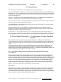
3.0 Signal Strength Peakup
This version of the software includes optional support for a signal strength peakup function after an auto
move to a satellite. The software version number indicates whether or not the software installed in a
given controller supports the peakup function. The controller displays it’s software version on power-up.
Controllers that have a software version number that ends with ‘5’, ‘6’, ‘7’, ‘8’, or ‘9’ support the peakup
function. Controllers that have a software version number that ends with ‘0’, ‘1’, ‘2’, ‘3’, or ‘4’ do not
support the peakup function. This section pertains to controllers that support the automatic peakup
function.
3.1 Enabling Peakups and Configuring Peakup Parameters
To use the peakup feature several controller CONFIG mode items have to be configured properly and
peakups have to be enabled.
3.1.1 Enabling Peakups
To implement the peaking function the controller requires an analog input voltage that varies with
received signal strength (0 to 10 volts DC max range). This voltage is typically provided by a receiver or
modem AGC (Automatic Gain Control) circuit. The interface of this analog voltage to the controller is
described in section two.
On controllers that support the peakup function, peakups can be enabled via the Peakup Enable
CONFIG mode item. When enabled, peakups will follow an automatic move either initiated via the front
panel or via certain commands received via the controller’s serial port.
Peakups initiated by the user via the controller’s user interface occur at the conclusion of automatic
move commands. At the completion of the automatic move, if peakups are enabled and the Peakup
related CONFIG mode items are valid, a peakup is initiated. Note that invalid Peakup related CONFIG
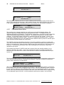
mode items will result in display of a flashing ‘PEAKUP CONFIG’ alarm message on the bottom row of
the controllers LCD.
3.1.2 Peakup Holdoff
When a peakup is initiated the controller will either immediately look for signal strength and begin a
peakup OR it will enter a 5 second wait interval depending on the value of the Peakup Holdoff Interval
CONFIG mode item. If the Peakup Holdoff Interval has a value of 0 the controller will begin a peakup
operation if the controller’s signal strength input is greater than the AGC C Band Threshold (if a C band
satellite was the target of the automatic move) or AGC K Band Threshold (if a Ku band satellite was the
target of the automatic move). If the Peakup Holdoff Interval is set to zero and signal strength above
the appropriate ‘Threshold is not available, the controller will not perform a peakup operation.
If the value of Peakup Holdoff Interval is 1 or greater (up to a maximum value of 300 seconds), at the
conclusion of the automatic move the controller will enter a 5 second wait interval. During this 5 second
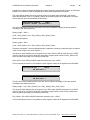
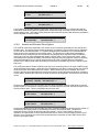
interval, ‘PEAKUP SETTLE’ will be displayed on the bottom row of the controller’s LCD (liquid crystal
display). The purpose of this interval is to allow the AGC input signal to settle. After the SETTLE
interval, the controller looks for signal strength. If signal strength is available the controller immediately
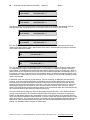
initiates a peakup. If signal strength is not available, the controller will display ‘PEAKUP HOLDOFF:
XXX’. XXX is initially the value of the Peakup Holdoff Interval CONFIG mode item (in seconds), it is
decremented once each second. If signal strength becomes available before the timer expires (reaches
zero) a peakup will occur, otherwise, a peakup will not occur.
3.1.3 Peakup Step Sizes
The most important peakup related CONFIG mode items are C Band Azim Step Size, C Band Elev Step
Size, Ku Band Azim Step Size, and Ku Band Elev Step Size.
Research Concepts, Inc. • 5420 Martindale Road • Shawnee, Kansas • 66218-9680 • USA
www.researchconcepts.com