1
80
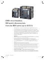
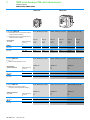
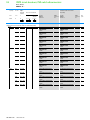
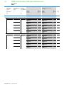
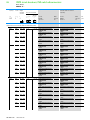
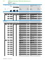
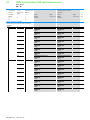
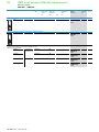
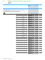
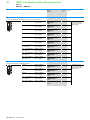
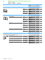
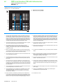
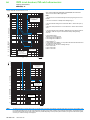
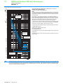
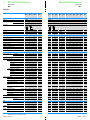
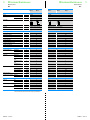
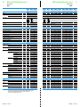
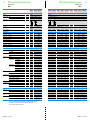
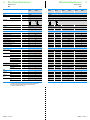
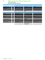
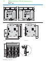
IZMX circuit-breakers, INX switch-disconnectors
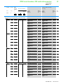
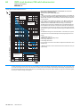
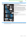
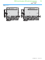
IZMX circuit-breakers, INX switch-disconnectors
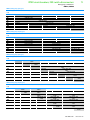
IZMX circuit-breakers
IZMX40…
81
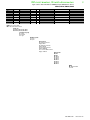
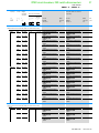
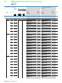
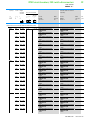
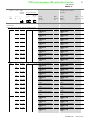
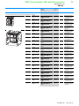
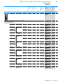
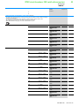
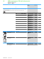
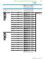
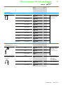
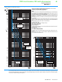
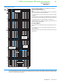
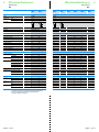
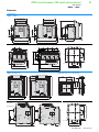
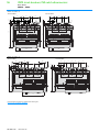
IZMX circuit-breakers
IZMX40…
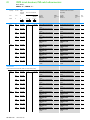
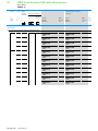
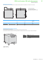
IZMX circuit-breakers
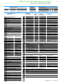
RES608...
IZMX40B...08...
RES610...
IZMX40B...10...
RES613…
IZMX40B...12...
RES616...
IZMX40B...16...
RES620...
IZMX40B...20...
RES625...
IZMX40B...25...
RES632...
IZMX40B...32...
RES640...
IZMX40B...40...
RES808...
IZMX40N...08...
RES810...
IZMX40N...10...
RES813…
IZMX40N...12...
RES816...
IZMX40N...16...
IEC/EN 60947
IEC/EN 60947
IEC/EN 60947
IEC/EN 60947
IEC/EN 60947
IEC/EN 60947
IEC/EN 60947
IEC/EN 60947
B
B
B
B
B
B
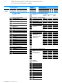
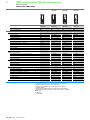
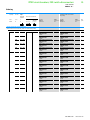
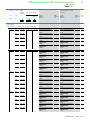
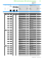
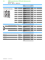
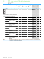
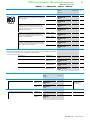
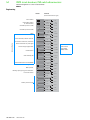
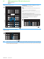
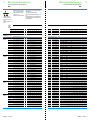
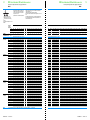
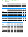
General
Standards
Ambient temperature
IEC/EN 60947
IEC/EN 60947
Storage
°C
-25 - +70 (device with LCD-display -20 - +70)
-25 - +70 (device with LCD-display -20 - +70)
Operating (open)
°C
-25 - +70 (device with LCD-display -20 - +70)
-25 - +70 (device with LCD-display -20 - +70)
Mounting position
30˚ 30˚
30˚ 30˚
30˚ 30˚
Utilization category
B
Protection type
IP20, IP55 with protective cover, IP41 with door
sealing frame
as required
as required
as required
IP20, IP55 with protective cover, IP41 with door sealing frame
as required
as required
as required
as required
as required
as required
as required
as required
as required
Direction of incoming supply
B
B
B
30˚ 30˚
B
B
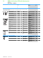
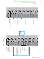
Main conducting paths
Rated current = rated uninterrupted current
I n = Iu
A
800
1000
1250
1600
2000
2500
3200
4000
800
1000
1250
1600
Rated uninterrupted current at 50 °C1)
Iu
A
800
1000
1250
1600
2000
2500
3200
40002)
800
1000
1250
1600
Rated uninterrupted current at 60 °C1)
Iu
A
800
1000
1250
1600
2000
2500
3200
36502)
800
1000
1250
1600
Rated uninterrupted current at 70 °C1)
Iu
A
800
1000
1250
1600
2000
2500
3200
35002)
800
1000
1250
1600
Rated impulse withstand voltage
Uimp
V AC
8000
8000
8000
8000
8000
8000
8000
8000
8000
8000
8000
8000
Rated operational voltage, max.
Ue
V DC
690
690
690
690
690
690
690
690
690
690
690
690
Use in IT electrical power networks up to U = 440 V
IIT
kA
50
50
50
50
50
50
50
50
50
50
50
50
III/3
III/3
III/3
III/3
III/3
III/3
III/3
III/3
III/3
III/3
III/3
III/3
Overvoltage category/pollution degree
Rated insulation voltage
Ui
V
1000
1000
1000
1000
1000
1000
1000
1000
1000
1000
1000
1000
Icm
kA
144
144
144
144
144
144
144
144
166
166
166
166
Icw
kA
66
66
66
66
66
66
66
85
85
85
85
85
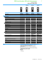
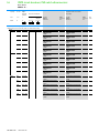
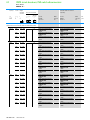
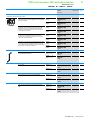
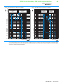
Switching capacity
Rated short-circuit making capacity
up to 440 V 50/60 Hz
Rated short-time withstand current 50/60 Hz
t=1s
Rated short-circuit breaking capacity Icn
IEC/EN 60947 operating
sequence Icu O-t-CO
IEC/EN 60947 operating
sequence Ics O-t-CO-t-CO
up to 240 V 50/60 Hz
Icu
kA
66
66
66
66
66
66
66
66
85
85
85
85
up to 440 V 50/60 Hz
Icu
kA
66
66
66
66
66
66
66
66
85
85
85
85
up to 690 V 50/60 Hz
Icu
kA
66
66
66
66
66
66
66
66
75
75
75
75
up to 1100 V 50/60 Hz
Icu
kA
–
–
–
–
–
–
–
–
–
–
–
–
up to 240 V 50/60 Hz
Ics
kA
66
66
66
66
66
66
66
66
85
85
85
85
up to 440 V 50/60 Hz
Ics
kA
66
66
66
66
66
66
66
66
85
85
85
85
up to 690 V 50/60 Hz
Ics
kA
66
66
66
66
66
66
66
66
75
75
75
75
up to 1100 V 50/60 Hz
Ics
kA
–
–
–
–
–
–
–
–
–
–
–
–
ms
30
30
30
30
30
30
30
30
30
30
30
30
ms
35
35
35
35
35
35
35
35
35
35
35
35
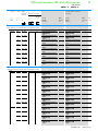
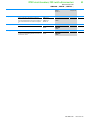
Operating times for ON
Total closing time
Operating times for OFF
Total opening time with shunt releases
ms
22
22
22
22
22
22
22
22
22
22
22
22
Total opening time with undervoltage releases
ms
37
37
37
37
37
37
37
37
37
37
37
37
Total trippinig time (until fault is fully cleared)
ms
45
45
45
45
45
45
45
45
45
45
45
45
Operations/h
60
60
60
60
60
60
60
60
60
60
60
60
Fixed mounting
W
90
90
135
225
285
300
480
750
90
90
135
225
Withdrawable units
W
135
120
180
300
345
450
720
1120
135
120
180
300
Maximum operating frequency
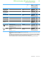
Heat dissipation at rated current In
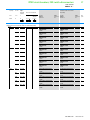
Weight
Fixed mounting
3-pole
kg
45
45
45
45
45
45
45
45
45
45
45
45
4-pole
kg
56
56
56
56
56
56
56
56
56
56
56
56
Withdrawable
3-pole
kg
69
69
69
69
69
69
69
69
69
69
69
69
(CB only)
4-pole
kg
86
86
86
86
86
86
86
86
86
86
86
86
Cassette
3 pole
kg
29
29
29
29
29
29
29
29
29
29
29
29
4 pole
kg
35
35
35
35
35
35
35
35
35
35
35
35
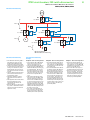
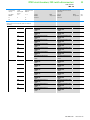
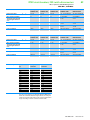
Notes
CA01305001Z-EN
1) Permissible
continuous current for circuit-breakers operating in switchboards at various internal ambient temperatures.
The switchboard’s internal ambient temperature should be estimated using the calculation methods of IEC regulation.
2) Rated continuous current stated applies only with 4 x 120 x 10 mm vertical terminal rails painted black.
The values are reduced by 100 A each with 4 x 100 x 10 mm.
www.eaton.com
CA01305001Z-EN
www.eaton.com