1
CIP2 Hardware Installation
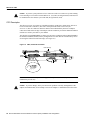
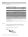
Caution To prevent damaging the PCA connector on the CIP2 by unintentionally disconnecting the
Y cable from the PCA connector, provide adequate strain relief for the heavy bus and tag cables that
attach to the PCA.
CIP2 Hardware Installation
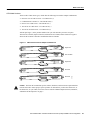
The following sections describe the procedures for installing or replacing the CIP2:
•
•
•
Removing a CIP2 or an Interface Processor Filler, page 31
Installing a CIP2, page 34
Attaching the CIP2 to the Channel, page 35
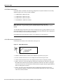
Caution To avoid unnecessary errors, read the section “Guidelines for Interface Processor Removal
and Installation” before removing or replacing a CIP2.
Before installing a newCIP2, ensure that your system meets the minimum software and microcode
requirements described in the sections “CIP2 Software, Hardware, and Microcode Prerequisites,” on
page 4, and “CIP2 Microcode Overview” on page 6.
While you can remove and install a CIP2 without turning off system power, we do recommend that
you administratively shut down CIP2 interface before insertion and removal. In any case, you must
follow the insertion instructions carefully; for example, failure to use the ejector levers or insert the
CIP2 properly can cause system error messages indicating a card failure.
Each unused interface processor slot contains an interface processor filler (which is an interface
processor carrier without an interface card) to keep dust out of the chassis and to maintain proper
airflow through the interface processor compartment.
If you install a new CIP2, select an empty interface processor slot and remove the interface processor
filler. If you replace a CIP2, you can retain the existing interface configuration by removing the
existing interface processor and installing the new one in the same slot; however, the new CIP2 must
have the same channel adapter configuration as the CIP2 you replaced.
Proceed to the section “Removing a CIP2 or an Interface Processor Filler,” on page 31, for
instructions on making an interface processor slot available for the new CIP2, then to the section
“Installing a CIP2,” on page 34, for the installation instructions. After the new CIP2 is secure, follow
the procedures in the section “Checking the CIP2 Installation,” on page 40, to verify that it is
installed and functioning properly.
30 Second-Generation Channel Interface Processor (CIP2) Installation and Configuration