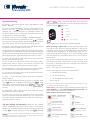
1
3) (Optional) Connect the Powermax to the telephone
line via terminals 2 & 5 on the BT socket, and the “Line” terminals
on Powermax. Alternatively, if you have a standard plug-in phone
lead remove the clear plastic (RJ11) plug and use the centre two
cores of the cable to connect to the line terminals (there is no
difference which way around these are connected).
LL If Broadband (ADSL) is enabled on the premises phone
line then you will need to fit a filter. Available from most
wholesalers.
LL Wireless PIR’s have a two minute sleep timer to save
battery life – On initial power up the unit will go through a
self test (LED flashing) then enter a walk test mode. If the
PIR has gone into sleep mode make each room vacant for
two minutes or open and close the lid before carrying out
the walk test.
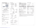
MCT-320 Door Contact has a built in reed switch, for use with the
magnet supplied.
MCT-320
4) Power-up the PowerMax by connecting the battery first,
which fits in to the compartment on the main panel, then connect
the lead from the transformer to the 9VAC terminals.
LL The backup battery may take an hour to reach full capacity,
during this period the panel will report “CPU Low Battery”.
LL Depending the status of the panel and accessories the
display will show [READY – MEMORY] or [NOT READY –
MEMORY]. At any time you can press the status button on
to find out the faults/
the keyfob, or repeatedly press
memory conditions that are outstanding.
To install the main transmitter to the door or window frame,
ensuring that the curved edge is facing the opening section. The
magnet should be installed on the opening section no more than
5mm from the transmitter.
LL If the gap between the MCT-320 and magnet is to great use
the 7mm plastic spacer, provided within the kit, to increase
the height of the magnet.
•
•
Zone 1 - Front Door Contact. ‘Delay 1’ to start the Entry timer
Zone 2 - Hall PIR. ‘Perimeter Follow’ to allow user to walk
through during entry time to disarm
MCS-730 Wireless Siren is installed using the four fixing screws
provided. Note the fifth
screw should be fitted for
the back tamper (EN50131
MCS-730
Grade 2 installations) using
the fixing point in the centre
below the peizo siren. The
MCS-730 can be fitted with
a second battery for extended life and also has a comfort LED
which can be enabled/disabled via the jumper link in the battery
compartment. See MCS-730 manual for more information.
•
Zone 3 - Living Room PIR ‘Perimeter’ which will trigger the
alarm once armed
LL Important – The panel selector link inside the MCS battery
compartment must be in the PM+ position.
•
Zone 4 - Upstairs PIR ‘Interior’ which will only trigger when
armed in the Away mode
LL Note up to two MCS sirens can be fitted to the PowerMax.
5) Before you Install the Accessories we recommend that you
carry out a diagnostic check which is in section 7 of this guide.
Each device is labelled with its zone number. Make sure you note
this before installing.
Additionally each sensor supplied in this kit is pre- programmed
for the following:
PIR motion sensors should be sited to ensure that they do not
face into direct sunlight, windows, strong sources of heat and cold
(i.e. heaters, radiators, cold drafts or ventilators). They should also
be mounted at the correct
height (between 1.8 –
NEXT/
2.4m) in a position, for
K-985 MCW PET sensors, away from
stairs and that does not
allow animals to move
within 1m of the device.
To install, remove the cover, unclip the PCB, drill and fit in to
position being careful not to over tighten the screw and distort
the backplate. Then refit the PCB in to the back plate ensuring the
back tamper switch sits on to the metal spring.
Enrol additional devices by firstly removing from their packaging
and opening the cases near the Powermax. Then, whilst in
installer mode (see section 1 Accessing the Installer mode) press
until ‘Enrolling’ is shown, press
then:For PIR Movement sensors, Door Contact, Glassbreaks, hand held
panic buttons etc :-
•
Press
•
until you get to the next available zone (as default
Press
this will be zone 5) which will be indicated by having no black
marker on the right of the screen.
•
•
Press
until [Enrol Sensors] is show on the screen. Press
. At [Set Sensitivity] press
, then
again.
. ‘Transmit now’ will be on screen.
Add the battery supplied to the sensor you wish to enrol to
this zone.