1
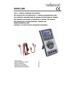
DVM1500
Continuiity measureme
ents
Rev. 01
Do
o not perform co
ontinuity measurrements on live circuits.
c
• Connectt the red test lead to the "VΩ
°CHz" jack and the black
b
lead
to the "C
COM" jack.
• Set the rotary switch to
.
• Press the FUNC button to select continuity test
t
.
• Connectt the test probes to
o the source being
g measured.
• When th
he measured resisttance is less than 40Ω a continuous beep is
produced and the resistan
nce value is showe
ed on the display. Should
S
the
measure
ed resistance exce
eed the current ran
nge or in case of an
a open
circuit, the
t
display will sho
ow “OL”.
Nota: Nev
ver perform continuity measurementts on a live circuit and make
sure all capacitors are com
mpletely depleted.
Diode measurements
m
Do
o not perform dio
ode measuremen
nts on live circuiits.
• Connectt the red test lead to the "VΩ
°CHz" jack and the black
b
lead
to the "C
COM" jack.
• Set the rotary switch to
.
• Press the FUNC button to select diode test
.
• Connectt the red test probe to the anode of the diode and the black test
probe to
o the cathode.
• The metter shows the forw
ward voltage drop of
o the diode. When
n the diode
is conne
ected with a revers
sed polarity, the display shows “OL”.
Notes:
o Neverr perform diode measurements on a live circuit and make sure
all cap
pacitors are complletely depleted.
o Measu
uring diodes that are
a part of a circuit might produce fa
aulty
resultts. Consider unmou
unting from the circuit.
Capacita
ance measurem
ments
Do
o not perform capacitance measu
urements on live
e circuits.
• Connectt the red test lead to the "VΩ
°CHz" jack and the black
b
lead
to the "C
COM" jack.
• Set the rotary switch to .
• Press the RANGE button to
o manually select the range.
• Connectt the test probes to
o the capacitor and read its value from the
display.
Notes:
o It take
es a few seconds before
b
the meter shows
s
the result. This
T
is
norma
al behavior.
o To inc
crease accuracy when measuring low
w capacitance valu
ues (<4nF),
first hold
h
the tips of the
e measuring probes together to dete
ermine the
capac
citance value of the
e test leads. Subtrract this value from
m the
measu
ured value of the circuit.
c
16.04.2010
10
©
©Velleman
nv