1
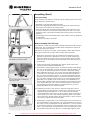
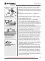
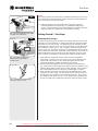
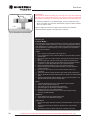
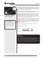
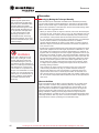
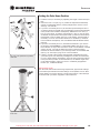
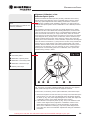
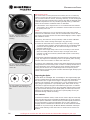
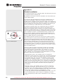
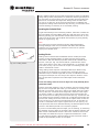
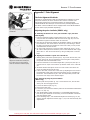
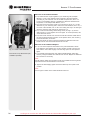
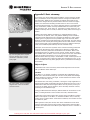
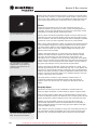
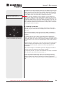
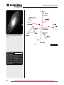
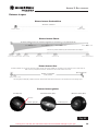
Maintenance and Service IMPORTANT NOTE: Do not force the 4 screws past their normal travel, and do not rotate any screw or screws more than 2 full turns in a counterclockwise direction (i.e., not more than 2 full turns in their „loosening“ direction), or else the diagonal mirror may become loosened from its support. Note that the diagonal mirror collimation adjustments are very sensitive: generally turning a collimation screw 1/2-turn will have a dramatic effect on collimation. 3. If the reflection of the diagonal mirror is not centered within the reflection of the primary mirror, adjust the 3 collimation screws located on the rear of the primary mirror cell. Fig 31b: The four collimation screws on the secondary mirror housing NOTE: There are 6 screws (Fig. 31c) on the primary mirror cell. The 3 knurled knobs are the collimation screws, and the 3 smaller thumb screws are locking screws. The locking screws must be loosened slightly in order to adjust the collimation screws. Proceed by „trial and error“ until you develop a feel for which collimation screw to turn in order to change the image in any given way. 4. P erform an actual star test to confirm the accuracy of steps 1 through 3. Using the 25mm eyepiece, point the telescope at a moderately bright (second or third magnitude) star, and center the image in the main telescope‘s field of view. 5. Bring the star‘s image slowly in and out of focus until you see several disks surrounding the star‘s center. If steps 1 through 3 were done correctly, you will see concentric (centered with respect to each other) circles (1, Fig. 32). knurled knob thumbscrew An improperly collimated instrument will reveal oblong or elongated circles (2, Fig. 32). Adjust the 3 collimating screws on the primary mirror housing until the circles are concentric on either side of the focus. Fig. 31c: The six collimation screws on the rear of the primary mirror cell. In summary, the 4 adjustment screws on the plastic diagonal mirror housing change the tilt of the secondary mirror so that it is correctly centered in the focuser drawtube, and so that the primary mirror appears centered when looking into the focuser. The 3 collimating knobs on the primary mirror change the tilt of the primary mirror so that it reflects the light directly up the center of the drawtube. Inspecting the Optics 1 2 Fig. 32: Correct (1) and incorrect (2) collimation viewed during a star test. A Note About the “Flashlight Test: If a flashlight or other high-intensity light source is pointed down the main telescope tube, the view (depending upon the observer’s line of sight and the angle of the light) may reveal what appears to be scratches, dark or bright spots, or just generally uneven coatings, giving the appearance of poor quality optics. These items are only seen when a high intensity light is transmitted through lenses or reflected off the mirrors, and can be seen on any high quality optical system, including giant research telescopes.The optical quality of a telescope cannot be judged by the “flashlight test;“ the true test of optical quality can only be conducted through careful star testing. Laser collimator: To make the collimation easier, a laser can be used to align the secondary mirror and the main mirror. Especially fast Newtonians (f/5 or f/4 systems) require precise collimation to deliver the best possible optical performance. It is recommended, to check the collimation prior to every observing or imaging session.A suitable laser collimator can be found with item number 4910200 in our product range. All Bresser Messier Newtonian telescopes have a center marking on the main mirror so a laser can be used for collimation. 21 Looking at or near the Sun will cause instant and irreversible damage to your eye!