1
Quick start-up
The temperature controller is ready for use. One control zone for one heater and one thermocouple for measurement of the actual value is set up for operation. The start-up of the control zone can be done in a few steps. (*) see
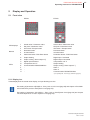
chapter ÓDisplay Loc)
ETR45
ETR46
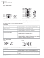
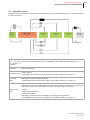
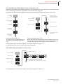
Step 1: Electrical connection
Step 1: Electrical connection
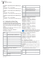
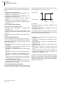
Ú Connect the thermocouple between terminal 10 and
11.
Ú A Solid State Relay (SSR) is used as a power control-ler. Notice the heat output at switching to select
the correct SSR.
To activate the Solid State Relay connect it to ter-minal 5(+) and 6(-) of the controller.
Ú Connect the heater with power supply and Solid
State Relay. Use ultra rapid micro-fuse or ultra ra-pid
automatic circuit breaker for fuse protection of the
heating circuit.
Ú Connect the power supply of the controller by ter-minal 1 and 2 (e.g. 230 VAC).
Notice necessarily the specification of the
power supply of the controller (85...250
VAC or 24 V)!
Provide fuse protection.
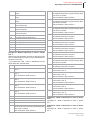
Ú Connect the thermocouple between terminal 10 and
11.
Ú A Solid State Relay (SSR) is used as a power control-ler. Notice the heat output at switching to select the
correct SSR.
To activate the Solid State Relay connect it to termi-nal 17(+) and 24(-) of the controller.
For the power supply of the control output
there must be an additional connection bet-ween terminal 1 and 16.
Ú Connect the heater with power supply and Solid State
Relay. Use ultra rapid micro-fuse or ultra rapid auto-matic circuit breaker for fuse protection of the heating
circuit.
Ú Connect the power supply of the controller by terminal
13 and 14 (e.g. 230 VAC)
Notice necessarily the specification of the
power supply of the controller (85...250 VAC
or 24 V)!
Provide fuse protection.
L
N
Delay-action Fuse
Fuse,
ultra-rapid
1
Heating
Unit
13
14
8
3
9
5
6
15
L
25
10
1
13
11
2
14
16
12
3
15
Temperature
Sensor
4
5
Temperature
Sensor
DOUT
1
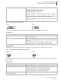
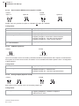
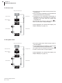
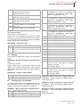
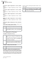
Step 2: Adjust sensor type *)
Fuse,
ultra-rapid
16
SSR
17
6
18
7
19
8
20
9
21
10
22
11
23
12
24
27
N
Delay-action
Fuse
26
DOUT
1
4
SSR
7
2
Heating
Unit
28
Step 2: Adjust sensor type *)
f
f
Ú Press button
repeatedly until SEn is shown in
the display.
or
.
Ú Choose sensor type with the buttons
Ú Confirm sensor type with
and return to actual/set
point value display with
.
Ú Press button
repeatedly until SEn is shown in the
display.
or
.
Ú Choose sensor type with the buttons
Ú Confirm sensor type with
and return to actual/set
point value display with
.
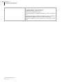
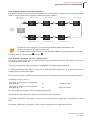
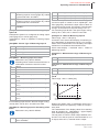
Step 3: Adjust set point *)
Step 3: Adjust set point *)
f
a
s d
a
Ú Press button
repeatedly until SP is shown in the
display.
and change set point with
and
.
Ú Press
Ú Confirm set point entry with button
and return
with
or
to actual/set point value display.
f
s d
s
f
d
f
a
s d
a
Ú Press button
repeatedly until SP is shown in the
display.
and change set point with
and
.
Ú Press
Ú Confirm set point entry with button
and return with
or
to actual/set point value display.
f
s d
s
f
d
Technical changes reserved
Rev. 1.01.07