1
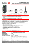
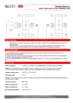
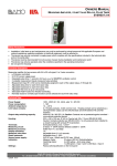
OPERATING INSTRUCTIONS TURBIDITY LIMIT-VALUE EVALUATION UNIT TURBISWITCH GS4 WITH MEASURING SENSOR OR IMMERSION PROBE Technical Data (continued): Reset hysteresis: Adjustable from 1 to 25% Sensor power supply: 15V DC, max. 100mA Display: Threshold value: Switching status: Range display: Adjustment: Rotary knob / pushbutton on front panel 2½-place LED, 5 x 7 pixel matrix display 1 blue LED = limit value exceeded 3 yellow LEDs = low / medium / high CE Mark: In accordance with low-voltage directive (2006/95/EC) and EMC directive (89/336/ECC) Controls – Rotary Knob / Pushbutton: Turn: The threshold value is adjusted at menu level 0. Hysteresis and time delay are selected at menu level 1. The desired numeric value is selected at menu level 2 (clockwise = + and anticlockwise = –). Press: Used to select submenus 1 and 2. Pushing the button in submenu 2 returns the display to menu 1. Note: If none of the controls are activated for 10 seconds, the device is automatically returned to menu 0. Possible Displays: Threshold value of 0 - 100% in the respective setting range (low / medium / high). TR: receiver error or receiver not connected TT: emitter error or emitter not connected In the case of correct, internal measured value processing, the LEDs on the emitter and the receiver must always blink (continuous illumination = error). Threshold Value Relay: Blue LED lights up = threshold has been exceeded Limit Value: 100% high 100% med 100% low 0% low/med/high Setting range: 3 x 0 to 100% Note: Switching to the next higher or lower measuring range is accomplished automatically by simply continuing to turn the adjusting knob. 100% in the low range is followed by 0% in the medium range. 100% in the medium range is followed by 0% in the high range. 100% in the high range is the highest possible threshold value. One yellow LED lights up in the low range. Two yellow LEDs light up in the medium range. Three yellow LEDs light up in the high range. whole detecting range Delay Time: Setting range of 0.1 to 9.9 s above/below the selected limit value wait for delay time to elapse the relay is then switched Default setting: 0.1 s BAMO IER GmbH Pirnaer Str. 24 D-68309 Mannheim, Germany Phone: +49 (0)621 84224-0 Fax: +49 (0)621 84224-90, e-mail: info@IER.de Internet: www.IER.de SU3547a.doc 10/12 2