1
SDB
907
Part N : 9722.01
o
SAT-TV Demodulator
DVB-S/-S2 → CI → ASI-TS & A/V
B
LINE
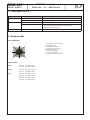
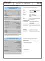
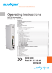
4. Front view
SAT-TV input
Operating voltage/
control bus
LED “STANDBY“ (red)
LED “READY“ (green)
LED “ADDR.“ (yellow)
Address selector
ASI-TS output
Video output
Audio output
5. Functional description
The SAT-IF input signal is fed to the DVB-S/ -S2 front end, where the selection of a transponder and its QPSK or 8PSK demodulation
are done. The data stream is routed by a switching matrix either to the Common Interface or directly to the DVB module consisting
of a demultiplexer and a MPEG decoder. An analogue video- and an associated stereo-audio signal are generated within the DVB
module. The video signal is filtered and the audio signal is processed by a DA converter afterwards. The SDB 907 supports the output
of additional services like Teletext, WSS, VPS and optional test lines and the display of subtitle. The analogue signal outputs were fed
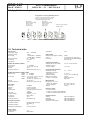
by buffer amplifiers (for the pin assigment of the audio socket see chapter 8). The audio outputs are balanced to ground. A respective
CA module with smart card, which is supported by the device, has to be used for descrambling.* Multi service decryption is possible
if there are not any restrictions by the CAM itself or by the service provider. The decryption of MPEG-4 services is supported. With this
module its possible to choose elementary streams of a service for decryption. So the ressources of the respective CAM/ smart card
combination can be used optimally. BISS decryption can be performed by activating the software option CKB 104. Supported are the
BISS mode 1 and the BISS mode E with entering the necessary Injected ID, but not the BISS mode E with the optional Buried ID. The
activation of the software option CKB 105 allows the output of the processed data stream on the ASI-TS connector. The multi service
decryption is enabled therby.
*
The design of the Common interface of this module is done according to DVB standards. Because of the dependencies in interaction of the DVB signals, CA modules and smart cards we can not assure a general functional capability for all application possibilities. Please contact our service
department for further assistance.
6. Adjustments
6.1 Adjustment with the Headend Controller
·Adjustment of the addresses at the Bus Extender BEB x00 and at the modules
·Activation of the programming mode on each module by selecting the line (BEB x00) and the module position (1... 15) at the
Headend Controller(HCB x00)
→ yellow LED illuminates until the beginning of the parameter adjustment
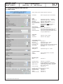
·Adjustment of the SDB 907 parameters (see chapter 10) → green LED is switched on
·After the programming the SDB 907 will be automatically switched into the operating mode
→ yellow LED flashes shortly/ green LED is switched on
6.2 Adjustment with the PC/ laptop
·Prerequisite for the remote programming is an “online connection” according the IP standard and an ethernet connection at the PC/ laptop
·Adjustment of the line/ position addresses at the Bus Extender BEB x00 as well as at the modules
·At the Headend Controller HCB x00 input IP address (default: 192.168.2.80)
·For “direct connection” between a PC and HCB x00 use crossover cable (RJ 45)
·For connection over a HUB use a normal straight throught patch cable
·Start-up HTML browser and put in IP address as target address
·If connected correctly the web interface will be opened on the pc and a blue LED (LINK) at the HCB x00 will be lit up.
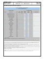
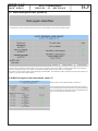
·All adjustments of the modules are specified on the web interface.
The manual instructions of the Headend Controller HCB x00 and the Bus Extender BEB x00 have to be considered!
3