1
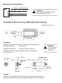
Electrical connections
Screen
IMM
interface chassis
Red
16.5 - 18.5 V dc
Blue
0V
Green
output signal
!
WARNING:
Wires must be connected as shown,
otherwise failure can occur.
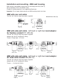
Installation and mounting - IMM cylindrical housing
Ø20,2
Ø20,0
(Ø0.795)
(Ø0.787)
Ø21
(0.83)
dimensions mm (in)
Ø6 (Ø0.23)
MINIMUM
0.8 (32)
15°
TO SUIT IMM
Grubscrews
Drill and tap the machine housing to line up with the clamping zone.
Clamping screw size
M4 maximum.
Clamping screw torque
0,5 Nm (0.37 lbf.ft) maximum.
WARNING:
Do not use cone
point screws for
clamping
!
The IMM is secured using flat ended grubscrews over clamping
zone marked x x x.
5 (0.19)
Ø20 (Ø0.78)
11,5
(0.45)
Clamping zone
13 (0.51)
5 (0.19)
IMM cable
Clamping
zone
13
(0.51)
20 (0.78)
11,5 (0.45)
3 (0.12)
47 (1.85)
75 (2.95)
Important
Pressure may be applied to the metal housing around the circumference, but
the plastic front face should not be subjected to direct pressure on installation.
Ø6 (Ø0.23)
Cable outlet