1
Installing the Video Matrix Switcher
6
Installing the Video Matrix Switcher
To install the VS-1616V, connect the following1 to the rear panel, as
required:
Power cord
Video input and output cables
Control Interface cables between switcher units, or PC (or other
controller), as section 6.6 describes
Set the dipswitches, as section 6.5 describes
Set the system variables using the MENU function, as section 8 describes
Using the VS-1616V unit and/or other 16x16 matrix switchers in the series2,
you can assemble the following kinds of systems:
A stand alone switcher (see section 6.1)
A multi-channel video switcher (see section 6.2)
An expanded matrix switcher (see section 6.3)
A system of interconnected switchers (see section 6.4)
6.1 Configuring a Stand Alone Switcher
Configure your VS-1616V unit as a stand alone switcher for:
Composite video (CV) (see section 6.1.1)
s-Video (Y/C) (see section 6.1.2)
YUV (RGB) (see section 6.1.3)
RGBS (see section 6.1.4)
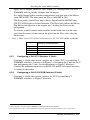
Table 4 defines the number of inputs and outputs for each signal
configuration:
Table 4: Stand Alone Switcher Configuration for CV, Y/C, YUV (RGB) and RGBS
Configuration Number of Inputs and Outputs
on a Stand Alone Unit
Composite
16x16
s-Video (Y/C)
8x8
YUV / RGB
5x5
RGBS
4x4
1 Switch OFF the power on each device before connecting it to your VS-1616V
2 Including the VS-1616A (a 16x16 analog balanced stereo audio matrix switcher), the VS-1616VD (a 16x16 digital video
matrix switcher), the VS-1616AD (a 16x16 digital audio matrix switcher), and the VS-1616RS (an RS-422 control signal
matrix switcher)
7