1
Table of contents:
1. Controller installation ............................................................................................................ 4
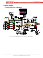
1.1. Layout diagram STAG-4 QBOX BASIC ............................................................................................................. 4
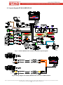
1.2. Layout diagram STAG-4 QBOX PLUS .............................................................................................................. 5
1.3. Semi-sequential control ..................................................................................................................................... 6
1.4. Full-group control ............................................................................................................................................... 6
1.5. Mounting the controller STAG-4 QBOX ............................................................................................................. 6
1.6. Selection of pressure regulator .......................................................................................................................... 6
1.7. Selection of injector nozzles .............................................................................................................................. 7
2. The AC STAG diagnostic program ....................................................................................... 7
2.1. Controller-computer connection ........................................................................................................................ 7
2.2. AC STAG version ............................................................................................................................................ 10
2.3. Main menu ....................................................................................................................................................... 10
2.4. Controller Parameters ...................................................................................................................................... 12
2.5. Signals, ingectors. LED switchboard ............................................................................................................... 16
2.6. Auto-calibration ................................................................................................................................................ 18
2.7. Oscilloscope .................................................................................................................................................... 19
2.8. Errors ............................................................................................................................................................... 19
2.8.1.
Errors of the gas controller ..................................................................................................................... 20
2.8.2.
Gas controller message .......................................................................................................................... 22
2.8.3.
Errors the ECU ........................................................................................................................................ 23
2.9. Multiplier map .................................................................................................................................................. 24
2.9.1.
Multiplier adjustment ............................................................................................................................... 27
2.10. RPM correction map ...................................................................................................................................... 28
2.11. Petrol portion map ......................................................................................................................................... 29
2.12. Gas temperature correction map ................................................................................................................... 30
2.13. Reducer temperature correction map ............................................................................................................ 30
2.14. Gas pressure correction map ........................................................................................................................ 31
2.15. Petrol map „B” ................................................................................................................................................ 31
2.16. Petrol map „G” ............................................................................................................................................... 32
2.17. Map acquisition state ..................................................................................................................................... 32
2.18. Injection time deviation map .......................................................................................................................... 34
2.19. MAP correction map (autoadaptation map) ................................................................................................... 34
2.20. OBDII/EOBD reader ...................................................................................................................................... 35
2.21. Assignment of gas injectors to banks ............................................................................................................ 37
2.22. Autoadaptacion .............................................................................................................................................. 39
AC S.A. all rights reserved. Under penalty of law and/or liability claims it is forbidden to copy, publish, distribute, make available and/or use in any way all or any part of information contained
within this document, in particular photographs, drawings, illustrations, trademarks, etc
2