1
maxon motor
Operating Instructions
1-Q-EC Amplifier DEC 24/1
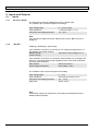
2. Technical Data
2.1.
Electrical data
Supply voltage VCC (ripple< 2 %) ................................................................................. 5…24 VDC
Max. output voltage at max output current ....................................................................VCC - 1.5 V
Continuous output current Icont ..................................................................................................1 A
Max. output current Imax.............................................................................................................2 A
Switching frequency of end stage ....................................................................................... 39 kHz
Max. speed (2-pole motor) ......................................................................................... 120 000 rpm
Internal motor chokes per phase.....................................................................150 µH, 1 A, 0.39 Ω
2.2.
Input
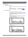
Speed .................................................................................................... Analogue input (0 … 5 V)
Resolution: 1024 steps
/Disable ....................................................................................TTL, CMOS (5 V) or switch to Gnd
Direction...................................................................................TTL, CMOS (5 V) or switch to Gnd
/Brake ......................................................................................TTL, CMOS (5 V) or switch to Gnd
Hall Sensor .......................................................................................................................... 1, 2, 3
2.3.
Output
Speed monitor.......................................................................Digital output signal (+5 VDC / 1 kΩ)
2.4.
Voltage output
2.5.
Motor connections
Hall sensors supply voltage “Vcc Hall” .....................................................4.5...5 VDC, max. 30 mA
“Motor winding 1”, “Motor winding 2”, “Motor winding 3”
2.6.
Trim potentiometers
Speed, Imax
2.7.
LED indicator
2.8.
Ambient temperature/humidity range
Operating and fault display: green LED
Operation .................................................................................................................... -10…+45°C
Storage ....................................................................................................................... -40…+85°C
No condensation ............................................................................................................ 20…80 %
2.9.
Protective functions
Blockage protection ....................Motor current limit if minimum speed is not maintained for 1.5 s
2.10.
Mechanical data
Weight........................................................................................................................ approx. 20 g
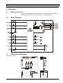
Dimensions (L x B x H) ...........................................................see dimension drawing, chapter 11
Mounting ............................................................4 hexagonal M3 distance pins with inner winding
Mounting hole separation............................................................................................ 49 x 28 mm
2.11.
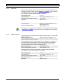
Terminals
Power / Signal
Screw terminal ..................................................................................................................... 7-pole
Pitch................................................................................................................................. 2.54 mm
2
suitable for wire cross-section......................................................... 0.14 ... 0.5 mm (AWG 26-20)
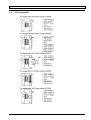
Motor and Hall sensors
Flat flexible cable connector, top contact style..................................................................... 8-pole
Pitch................................................................................................................................... 0.5 mm
or
Flat flexible cable connector, top contact style................................................................... 11-pole
Pitch...................................................................................................................................... 1 mm
or
Pin connector with snap-in locking device ........................................................................... 8-pole
Pitch................................................................................................................................... 2.5 mm
or
Screw terminal ..................................................................................................................... 8-pole
Pitch................................................................................................................................. 2.54 mm
2
suitable for wire cross-section......................................................... 0.14 ... 0.5 mm (AWG 26-20)
September 2009 edition / document number 555874-04 / subject to change
maxon motor control 3