1
IrDA
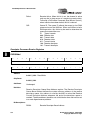
17.5.1.2 4.0 Mbps FIR Frame Format
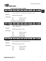
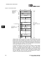
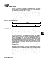
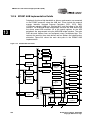
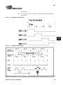
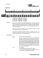
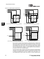
When the 4.0 Mbps transmission rate is used, the high-speed serial/parallel
(FIR) interface within the FIR is used along with the 4PPM bit encoding. The
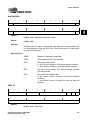
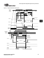
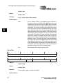
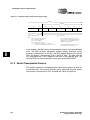
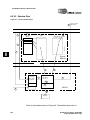
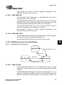
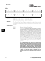
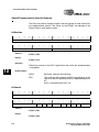
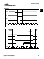
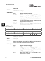
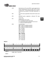
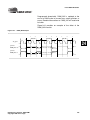
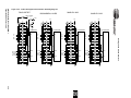
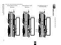
high-speed frame format shown in Figure 17-4 shown below, is similar to the
SDLC format with several minor modifications: the start/stop flags and CRC
are twice as long and instead of one start flag, a preamble and start flag of
differing length are used.
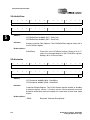
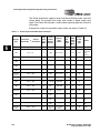
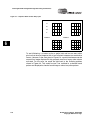
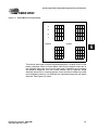
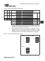
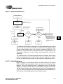
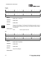
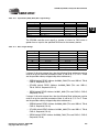
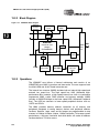
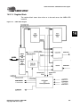
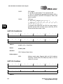
Figure 17-4. IrDA (4.0 Mbps) Transmission Format
64
symbols
8
symbols
4 DDs
(8 bits)
4 DDs
(8 bits)
8180 DDs max
(2045 bytes)
16 DDs
(32 bits)
8 symbols
Preamble
Start Flag
Address
Control
(optional)
Data
CRC-32
Stop Flag
Start Flag
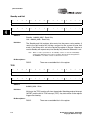
|0000|1100|0000|1100|0110|0000|0110|0000|
|0000|1100|0000|1100|0000|0110|0000|0110|
Preamble
17
Stop Flag
|1000|0000|1010|1000|... repeated 16 times
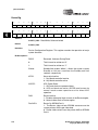
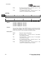
The preamble, start and stop flags are a mixture of symbols which contain
either 0, 1, or 2 pulses within the four time slots. Symbols with 0 and 2 pulses
are used to construct flags since they represent invalid data bit pairings (one
pulse required per symbol to represent one of four bit pairs). The preamble
contains sixteen repeated transmissions of the four symbols: 1000 0000 1010
1000, the start flag contains one transmission of eight symbols: 0000 1100
0000 1100 0110 0000 0110 0000 and the stop flag contains one transmission
of eight symbols: 0000 1100 0000 1100 0000 0110 0000 0110. The address,
control, data and CRC-32 all use the standard 4PPM DDs described above.
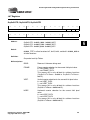
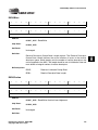
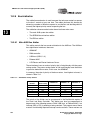
17.5.1.2.1 Address Field
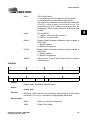
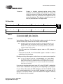
The 8 bit address field is used by a transmitter to target a select group of
receivers when multiple stations are connected to the same set of serial lines.
The address allows up to 255 stations to be uniquely addressed (00000000b
to 11111110b). The global address (11111111b) is use to broadcast messages
to all stations. Serial port 1 contains an 8 bit register which is used to program
a unique address for broadcast recognition as well as a control bit to
enable/disable the address match function. Note that the address of received
frames is stored in the receive buffer along with normal data and that it is
transmitted and received starting with its LSB and ending with its MSB.
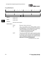
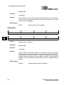
17.5.1.2.2 Control Field
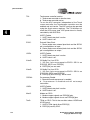
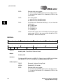
The IPC control field is 8 bits and is optional (as defined by the user). The FIR
does not provide any hardware decode support for the control byte, but
instead treats all bytes between the address and the CRC as data. Note that
596
EP9307 User’s Manual - DS667UM1