1
259
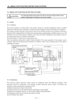
Das folgende Statusdiagramm beschreibt die Start-/Stop-Funktion der Steuerwort-(CW) und Statuswort- (SW) Bits für das ABB-Drives-Profil.
Von jedem Zustand
Von jedem Zustand Von jedem Zustand
Not-Aus
OFF2 (CW Bit 1=0)
Nothalt
OFF3 (CW Bit2=0)
(SW Bit5=0)
OFF3
ACTIVE
OFF2
ACTIVE
(SW Bit4 =0)
Fehler
FEHLER
(SW Bit3=1)
(CW Bit7=1)**
n(f)=0 / I=0
Von jedem Zustand
OFF1 (CW Bit0=0)
(SW Bit1=0)
INPUT POWER OFF
OFF1
ACTIVE
n(f)=0 / I=0
(SW Bit6=1)
(CW Bit0=0)
Spannung EIN
A B* C D
NOT READY
TO SWITCH ON
(SW Bit0=0)
(CW xxxx x1*xx xxxx x110)
(CW Bit3 =0)
(SW Bit2 =0)
SWITCH-ON
INHIBITED
OPERATION
INHIBITED
READY TO
SWITCH ON
BETRIEB GESPERRT
(SW Bit0=1)
(CW= xxxx x1*xx xxxx x111)
B* C* D*
READY TO
OPERATE
(CW Bit4=0)*
(SW Bit1=1)
(CW Bit3=1 und
SW Bit12=1)
OPERATION
ENABLED
C D
(SW Bit2=1)
A
(CW Bit5=0)
(CW=xxxx x1*xx xxx1* 1111
d.h. Bit4=1)*
Status
Statusänderung
D
Im Beispiel beschriebener Pfad
CW = Steuerwort
(CW Bit6=0)
SW = Statuswort
RFG = Rampenfunktionsgenerator
I = Par. 0104 STROM
f = Par. 0103 AUSGANGSFREQ
n = Drehzahl
* Wird nur von dem Profil ABB DRV FULL
unterstützt.
** Der Statuswechsel tritt auch dann auf,
wenn der Fehler von einer anderen Quelle
(z.B. Digitaleingang) zurückgesetzt wird.
RFG AUSGANG
ENABLED*
B*
(CW=xxxx x1*xx xx11* 1111
d.h. Bit5=1)
RFG: ACCELERATOR
ENABLED
C
(CW=xxxx x1*xx x111* 1111
d.h. Bit6=1)
OPERATING
(SW Bit8=1)
D
Feldbus-Steuerung mit dem integrierten Feldbus