1
d )
Pa ided
ng Not Prov
i
t
un l (
Mot Wal
n
r
Fro
ade
He cket
on
Bra
6
QuickStart
Front Idler
2
IMPORTANT: This QuickStart is intended to highlight a typical installation. These instructions are not intended to be comprehensive. Since each application is unique, it is the responsibility of the purchaser,
designer, installer and end user to ensure that the total door system is safe for its intended use. Please consult the manual and/or a qualified technician for further information.
1st
2nd
for the model T door operator
Typical Mid-Span
Support Bracket
5
Inside the Electrical Box
(Not Provided)
Pivot Pin
and Cotter Pins
3
7
10 Limit Switches
5
Open Side of Straight Arm
Take-Up
Bolt
14 AWG Minimum
Retaining
Plate
CLO
SE
Limit Nuts
Follow ALL national and local electrical codes
9 Power Wiring
Three Phase Connection
N
OPE
L1
Arm Assembly
1
Power Wiring
ONLY!
HOT NEUTRAL EARTH
Push
8
L3
Single Phase Connection
G
SIN
SEN
ad
g Provided)
n
i
t
un Not P
Mooor (
D
on
L2
DEDICATED CIRCUIT
POWER
WIRING
USE COPPER WIRE ONLY
Direction Limit Nut Will Move During Travel
L1
L2
Power Wiring
ONLY!
Nylon Locking Nut
Pivot Bolt
DEDICATED CIRCUIT
POWER
WIRING
USE COPPER WIRE ONLY
Door
Bracket
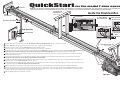
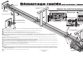
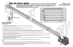
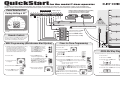
1 Install the track spacers down the track (as shown). The nylon pad on the spacer bracket must face up. (Two -1" bolts/nuts per spacer)
7
Typical Mounting Brackets
2 Install the front idler in the second hole from the end of the track. (Two -1" bolts/nuts with lock washers)
(Not Provided)
3 Slide the trolley into the tracks so that the take-up bolt will be facing toward the operator.
4 Secure the operator to the tracks using the L-slot and the 3rd hole for each track. (Four -1" bolts/nuts)
5 Connect the chain to the trolley carriage connection on the door end. Connect the take-up bolt on the other end and adjust chain accordingly. A properly adjusted chain will sag
about 3 inches at the mid-point. If necessary, remove links from the chain to achieve proper adjustment. (Two nuts and a lock washer, two master links)
6 Provide a mounting pad for the header bracket to attach to the front wall. Then use the pivot pin and cotter pins to secure the track assembly to the header bracket (with the
L-Sl
1
ot
operator remaining on the floor).
L-Sl
ot
7 Secure some mounting brackets to the operator. Pivot the operator up until track assembly is horizontal with the header bracket then secure the brackets to the ceiling.
If the track is longer than 15 feet, use of a mid-span support bracket is recommended.
4
4
4
3rd
8 Assemble the curved and straight arm as shown making sure the open side of the notch on the straight arm faces the door, (Two -1" bolts/nuts). Attach arm assembly to the
door bracket with a 1" bolt and nylon locking nut so the bolt can pivot.
4
3rd
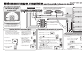
9 Run the power wires through the power wiring conduit hole in the electrical box enclosure. Connect the power to the operator. Connect the earth ground to the ground screw in
the electrical box enclosure. Follow ALL national and local electrical codes.
10 Adjust the limit switches to open and close door properly. Make sure the limit nuts are positioned between the limit switches before proceeding with adjustments.
Clut
ch
11 Remove cotter pin from nut on the clutch shaft. Back off clutch nut until there is very little tension on the clutch spring. Tighten clutch nut gradually until there is just enough
tension to permit the operator to move the door smoothly but to allow the clutch to slip if the door is obstructed. When the clutch is properly adjusted, it should generally be
possible to stop the door by hand during travel. Reinstall cotter pin when finished.
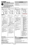
12 Radio programming instructions inside cover of operator.
PO
WE
RW
IR
IN
G
9
11
G
IN
IR
LW
RO
NT
CO
Operator