1
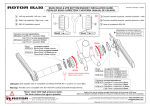
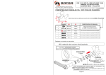
#2. Drive-side Assembly Installation.
#4. Preload adjustment.
Grease
the cone
of the spindle
#4.1 Eliminate
lateral play by
tightening
clockwise the
preload nut by
hand.
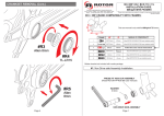
SPACER
11.5mm
#4.1
*
ONLY NEEDED
WITH BB30
FRAMES
(BEARINGS ARE
PRESSED
DIRECTLY INTO
THE FRAME).
IN PRESS FIT 30
FRAMES THE
CUPS REPLACE
BOTH THE
BEARING AND
SEAL.
*
BEARING
30x42x7
(Not included)
#4.2 Lock the
preload nut by
tightening the
pinch bolt
clockwise to
1.2Nm with a
2.5mm allen
wrench.
#4.2
Allen 2.5mm
1.2Nm
*
SEAL
1.6mm width
(Not included)
#3. Fixing of Drive-side Assembly.
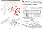
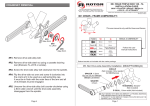
CRANKSET REMOVAL
#R1. Remove drive-side alloy bolt.
#R2. Remove drive-side steel nut using a cassette lockring
tool (Shimano TL-LR15 or similar).
Allen 8mm
35 Nm
#R3. Screw the drive-side alloy bolt clockwise into the spindle.
#R4. Flip the drive-side nut over and screw it clockwise into
the crank arm to be used as a self-extracting cap.
It must be in flush with the outer face of the arm and all
of its threads must be engaged.
Tighten drive-side alloy bolt to 35 Nm
using an 8mm allen torque wrench.
Page 2
#R5. Unscrew the drive-side alloy bolt counter-clockwise using
a 8mm allen wrench until the drive-side assembly
disengages from the spindle.
Page 3