1
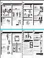
3 -2 Mount the two water inlet brackets on the wall (Continued)
7 Install the lavatory
5 -1 Install the drain assembly to the lavatory.
Remove all the protective covers.
2. Carefully place the lavatory into the cut-out. For
proper installation, two people may be required to
lift and position the lavatory.
Turn it clockwise (about 45°) and pull the grid unit out of the cross-bar.
Connect the hot/cold water supply pipe with the water inlet brackets.
Not
included
Not
included
Copper tube
Nut
Flexible hose
Nut
Cone washer
●Be sure to cut the hose
carefully with a cutter, so the
surface is square.
●If the spout connecting hose is
too long, cut it to a proper
length.
8 Attach to the counter
Caution
Fasten the hook bolts in the
order shown
Friction ring
Packing
Caution
Caution
If Grid unit hook is trapped, restore the grid unit, Then turn it
clockwise again, while pulling it slowly out of the cross-bar.
Pull
Grid Unit
Drain
Assembly
After placing packing, attach the
controller to the water inlet bracket,
and then fix them with the nuts as
shown in the figure.
Hook bolt
Washer
Butterfly nut
Notch
After seperating the grid unit and drain assembly
body, install the drain assembly body on to the
Lavatory.
Then apply the Plumber’s Putty or Silicone caulking
around the lavatory waste oulet.
Remove all the protective
covers.
9 Apply Caulking
Horizontal hole
Apply caulk around the perimeter of the washbasin then wipe off excess. Allow to dry
for 30 minutes.
10 Drawing of finished model
● Check that the spout hose is
firmly inserted.
● Check that the spout hose is
not folded.
● Check that the hose clamp is located
at the right position.
● It is imperative to connect the spout
with hose clamp.
Hose clamp shall be fixed right over
the controller water inlet
Hose clamp
GOOD NOT GOOD
Insert the vinyl cord (white) with connector
and make sure that you hear the click sound.
Controller
Packing
Controller water inlet
12 Fix the connector
lavatory
Packing is located on the water
inlet bracket.
Be careful that the
hose is not folded
Caution
Do not use tools. Using tool may result in
overtighting and cause product damage
Grid unit hook
Caution
Fasten the butterfly nut by hand
Cross bar
Draining
assembly body
4 Connect the controller to the water inlet brackets.
hose
Fix the hose with hose clamp.
Caution
Copper pipe
Make sure Hot goes on the left side.
Pay attention to the cut
section
Spout connecting
hose
Spout connecting
Hose clamp
Grid unit
Caution
90°
Insert the spout connecting hose into
the controller water inlet.
Grid cup unit
Flexible hose
Cut the spout connecting hose
to a proper length.
Cut the spout connecting hose to a proper
length that reaches controller water inlet
without being stretched.
1. Cut the countertop using the template provided.
Detach the grid unit by pulling it.
Caution
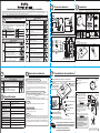
11 Connect spout connecting hose.
Click!
Nut
Water inlet
senser cord
Caulking
Apply Plumber’s Putty
or Silicone caulking
(around the lavatory waste outlet)
Check the following
5 -2 Install the drain to the
Lavatory (Continued)
6 Apply packing material. Make sure surface is free of dirt
and dust.
Grid unit
Lower the grid unit into the
drain assembly body
Now check that the stud at
the bottom of the cap is
positioned with the slit
on the Lavatory.
・Peel off the lining of the packing material, then stick the packing material to the
bottom of the lavatory.
13 Install the controller cover
14 Insert the power plug
After confirming the controller is securely
attached and confirming the controller is
firmly mounted, install the controller cover.
Insert the power plug in the wall
outlet.
Cover
Power plug
Turn the grid unit counterclockwise
while putting the Grid hook unit into the
cross bar.
Packing material
(large)
Notch
Angle
To make sure that the Grid unit is properly
placed on cross-bar, pull it upward.
Caution
Grid
unit
Caution
● Apply the small packing material
to the rear part of the lavatory,
be sure there is no clearance
between the large and small
packing material.
● Appply the packing material so that
it match with the inner edge of the
lavatory.
Packing material
(small)
Match here
If you can pull it out, repeat
installation procedure.
If the Grid unit is hooked to cross-bar and cannot be
pulled out, then push in the grid unit firmly until you hear
a click.
Packing material (small)
Grid
unit
Click!
Push until you
hear a click
Close the stop valve with hand.
Use the open/close tool to remove the strainer cover.
Perform the follow checks after installation.
1) Check for water leakage
Open the stop valve and check for water leakage.
Cold
3. Cleaning of the strainer
1.Checking after installation
Packing material
(small)
Hot
If water temperature goes opposite direction,confirm if the
hot and cold water connection is correct.
Function Test
Grid unit
Drain Assembly
body
Cross bar
The water temperature has been factory set to 97°F
(36˚C).
Temperature
Depending on the water supply pressure or other control
handle
site conditions, water temperature may not be
kept as specified. At this time, use the handle to
adjust the temperature.
Caution
Slit on the Lavatory.
Drain
assembly
2. Temperature Adjustment
About 15-3/4”
(400mm)
2) Operation
<Check the body dectection sensor>
●Insert the power plug to the AC outlet. Then, walk to the
. lavatory counter and when you are approximately 15-3/4”
(400mm) away from the counter, the LED light is ON.
<Check the hand washing sensor>
●Place your hands under the faucet, water begins to flow.
●Water will automatically stop in 1-2 sec later after your hands are removed.
● For safety and conservation reasons, water will stop
automatically after 60s of detection each use.
Hot/cold
<Check the switches>
switch
●Water flows when Start/Stop switch is pressed.
Start/Stop
●To stop the water flowing, press the switch again.
switch
●It will stop automatically after 50 seconds if switch is left ON.
●When hot/cold switch is pressed, LED switch turns red. Water reaches its
optimal temperature
●Temperature will restore by pressing it again; LED turns back to blue.
If the product does not operate properly, contact TOTO or your plumbing contractor.
-Clean the strainer regularly after installation.
Strainer
If the strainer is blocked, the flow becomes weak,
and the product will not function properly. Open/close tool
Strainer cover
4. Adjustment of flow rate
The flow controller regulates flow rate to 1.7 gpm
(6.5L/min) and there is no need to adjust the flow rate.
Use the product with the stop valve fully opened.
Close
Open
But when water flow is too strong, adjust the flow rate
by turning the stop valve clockwise.
Stop valve
The water appears cascade with water
flow rate of more than 1.45 gpm (5.5 L/min).
The Instruction Manual attached to the delivery must be
provided to the customer.