1
6
5
4
3
1
5205A
2
1
1
2
3
4
5
6
7
8
9
10
15 mm
(0.591 in.)
F
G
H
J
DO
DO
DI
DI
Masse
*
Remote IN
Type: IBS CT DIO 24/16-T
INTERBUS
4
3
Remote OUT
UL RC BA RD
24 V DC
Remote IN
Remote OUT
K
L
M
RBST
VCC
X
5 mm (0.197 in.)
30 mm
(1.181 in.)
A
B
DO
DO
DI
DI
Masse
A
B
C
D
E
1
2
3
4
5
6
7
8
9
10
E
US
xx
+24V
0V
UL+
UL-
Y
+ 24 -V DC
2
B
A
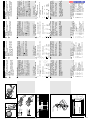
Remote OUT-Stecker
Verdrahtung der MINI-COMBICON
n
o
RC
BA
RD
xx
E
US
UL
6
Anzeigeelemente
Modul arbeitet einwandfrei, wenn alle
grünen LEDs leuchten.
grün
Versorgungsspannung für die
Modulelektronik
grün
Fernbus-Kabel-Check
grün
Bus aktiv
rot
Fernbus abgeschaltet
gelb
Status je Ein-/Ausgang
rot
Fehler je Gruppe
grün
Versorgungsspannung je
Gruppe
Informationen zur Anschlussbelegung
der Steckerleisten für die Ein- und
Ausgänge entnehmen Sie bitte dem
Datenblatt.
Remote OUT connector
Cabling MINI-COMBICON
e
n
t
n
3 - Remote OUT connector
4 - Remote IN connector
+24 V
RC
BA
RD
xx
E
US
UL
6
5
yellow
gray
shield
0V
Indication elements
Module is working correctly when all
green LEDs light up.
green Supply voltage for the
electronics module
green Remote bus cable check
green Bus is active
red
Remote bus disabled
yellow Status per input/output
red
Error per group
green Supply voltage per group
Please refer to the data sheet for more
information
about
the
terminal
assignment of the I/O connectors.
Plugging the remote bus connectors
Place the wired MINI-COMBICON
connectors with the coding tabs at the
bottom onto the corresponding terminal
strips.
Remote IN - incoming remote bus
Remote OUT - outgoing remote bus
DO
DI
UL-
Remote IN connector
DO
green
DI
pink
Ground brown
UL+
Y
L, M (*) Insert bridge if another device follows
X
4
o
p
m
o
gelb
grau
Schirm
0V
Aufsetzen der Fernbusstecker
Setzen Sie die verdrahteten MINICOMBICON-Stecker entsprechend den
Codiernasen auf die entsprechenden
Anschlussleisten.
Remote IN - ankommender Fernbus
Remote OUT - weiterführender Fernbus
DO
DI
c
e
il n
5
DO
grün
DI
rosa
Masse braun
+24 V
UL+
UL-
Remote IN-Stecker
Y
L, M (*) Brücke legen, falls weiterer Teilnehmer folgt
X
4
3 - Remote OUT-Stecker
4 - Remote IN-Stecker
Français
3
Connecteur interstation OUT
Câblage du MINI-COMBICON
+24 V
UL-
0V
Connecteur interstation IN
BA
RD
xx
E
US
RC
UL
6
Eléments d'affichage
Le module fonctionne correctement si
toutes les LED vertes sont allumées.
verte
Tension d’alimentation pour
le module électronique
verte
Contrôle câble bus
interstation
verte
Bus actif
rouge Bus interstation déconnecté
jaune Etat par entrée/sortie
rouge Erreurs par groupe
verte
Tension d'alimentation par
groupe
Pour de plus amples informations
relatives au brochage des connecteurs
E/S, cf. la fiche technique.
vert
DO
jaune
DO
DI
rose
DI
gris
Terre brun
blindage
Mise
en
place
des
connecteurs
5
interstation
Procédez à la connexion des connecteurs
MINI COMBICON câblés conformément
aux nez de codage.
Remote IN - bus interstation entrant
Remote OUT - bus interstation de
prolongation
UL+
Y
L, M (*) Pontage, si un autre abonné suit
X
4
3 - Connecteur interstation OUT
4 - Connecteur interstation IN
Montage des câbles de bus
Dénudez la gaine extérieure du câble,
raccourcissez la tresse de blindage puis
posez-la autour de la gaine extérieure du
câble (1). Enlevez le film de protection et
coupez le fil blanc (2).
Equipez d'embouts les extrémités des fils
dénudées.
Câblez les connecteurs (3,4) selon la
figure 4 .
Fixez la bride de blindage aux contacts 3
et 10 des connecteurs. Elle sert
simultanément de bride de serrage.
Montage
Placer le module par le haut sur le rail (A),
puis le presser vers le bas (B).
2 Démontage
Saisir la patte avec l’outil, tirer vers le haut
(A) et enlever le module à la verticale vers
le haut (B).
1
m
o
c
.
s
Installing the bus cables
Strip outer cable sheath, shorten braided
screen and fold it back over the cable
sheath (1). Remove protective foil and cut
off the white conductor (2).
Fit ferrules at the conductor ends.
Wire the connectors (3,4) according to
Figure 4 .
Connect shield clamp to contacts 3 and
10 of the connector. The clamp ensures a
proper strain relief.
Montage der Buskabel
Isolieren Sie den Kabelaußenmantel ab,
kürzen Sie das Schirmgeflecht und legen
Sie es um den Kabelaußenmantel (1).
Entfernen Sie die Schutzfolie und
schneiden Sie die weiße Ader ab (2).
Versehen Sie die abisolierten Aderenden
mit Aderendhülsen.
Verdrahten Sie die Stecker (3,4) nach
Bild 4 .
Befestigen Sie die Schirmschelle an den
Kontakten 3 und 10 der Stecker, sie sorgt
gleichzeitig für die Zugentlastung.
3
3
English
Installation
Place module on rail (A) from above and
press down firmly (B).
2 Removal
Insert a tool in the release tab and pull
gently outward (A). Pull up on pliers to
push release tab down and remove
module from rail (B).
1
Deutsch
Montage
Setzen Sie das Modul von oben auf die
Schiene (A), drücken Sie es dann nach
unten (B).
2 Demontage
Fassen Sie mit einem Werkzeug in die
Lasche, ziehen Sie es nach oben (A) und
ziehen Sie das Modul senkrecht zur
Schiene ab (B).
1
Italiano
Cablaggio
dei
connettori
COMBICON
Connettore remote OUT
3 - Connettore remote OUT
4 - Connettore remote IN
MINI-
Montaggio dei cavi bus
Isolate la guaina di protezione esterna,
accorciate la calza schermante e
posizionatela intorno alla guaina di
protezione esterna (1). Togliete la
pellicola di protezione e tagliate il
conduttore bianco (2).
Applicate sulle parti terminali isolate dei
conduttori le teste per cavo.
Cablate i connettori (3,4) in conformità
con la figura 4 .
Fissate la fascetta di schermatura sui
contatti 3 e 10 dei connettori; essa
provvede allo stesso tempo anche allo
scarico della trazione.
RC
BA
RD
xx
E
US
UL
6
5
0V
giallo
grigio
schermo
Elementi di visualizzazione
Il module funziona senza problemi
quando tutti i LED verdi sono accesi.
verde Tensione di alimentazione
per il modulo elettronica
verde Check cavo bus remoto
verde Bus attivo
rosso Bus remoto disinserito
giallo Stato di ogni ingresso/uscita
rosso Errori per gruppo
verde Tensione di alimentazione
per gruppo
Nel
scheda
dati
troverete
le
informazioni relative all’assegnazione
dei collegamenti dei connettori per
ingressi ed uscite.
Applicare i connettori di bus remoto
Inserite i connettori MINI-COMBICON
cablati, in conformità con le sporgenze di
codificazione, sui rispettivi listelli di
collegamento.
Remote IN - bus remoto di ingresso
Remote OUT - bus remoto di uscita
DO
DI
UL-
+24 V
UL+
verde
DO
DI
rosa
Massa marrone
Connettore remote IN
Y
L, M (*) Applicare un jumper se segue un
altro modulo
X
4
3
Montaggio
Posizionare il modulo dall’alto sulla rotaia
(A) e spingere verso il basso (B).
2 Smontaggio
Inserire un utensile nell’apertura, tirare
verso l’alto (A) ed estrarre il modulo in
senso verticale rispetto alla rotaia (B).
1