1
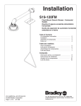
S19-430A, S19-430DInstallation IMPORTANT Read this installation manual completely to ensure proper installation, then file it with the owner or maintenance department. Compliance and conformity to drain requirements and other local codes and ordinances is the responsibilityof the installer. Installation Packing List IS TH SIDE UP • • • • Separate parts from packaging and make sure all parts are accounted for before discarding any packaging material. If any parts are missing, do not begin installation until you obtain the missing parts. Flush the water supply lines before beginning installation and after installation is complete. Test the unit for leaks and adequate water flow. Main water supply to the eyewash should be “ON” at all times. Provisions shall be made to prevent unauthorized shutoff. Da Da te Da tum te Sig ned Sig ned ned P.O TES . Box DIE ESS SEST THI 309 Tes AI S , Me Rep t-op HEBGER UNI Ven ort nom DO ÄT T EAC 1ST dur til(e anyera te MA one H Tes ch ) val DAI WÖ WE e sig Un wö ma ve( RE CHE EK Fal un ne t le ters che lfun s) ls, NTL rap en fon WI chr ntli ctio eac ICH por basctio 530 ns h ift. ch t imm. nne ZU immwe 51 Jeg im S'il ek me PRÜ Tes edi and édi y à nt lich tbe FEN Sig ate ate que des e Stö trie Un ned . ly. sig me lqu val n Sig ter nt. e ves run b prü bel g cho ne sch ow sof fen rift . se cha ort , bes qui que Da me ne sem ldetäti Da te va ain n. gt Da te pas e te Sig fait et R The ANSI Z358.1 standard requires an uninterrupted supply of flushing fluid. Bradley plumbed emergency fixtures require a minimum of 30 PSI (0.21 MPa) flowing pressure. Flushing fluid should be tepid per ANSI Z358.1. The inspection and testing results of this equipment should be recorded weekly to verify proper operation. This equipment should be inspected annually to ensure compliance with ANSI Z358.1. Workers who may come in contact with potentially hazardous materials should be trained regarding the placement and proper operation of emergency equipment per ANSI Z358.1. P.O. BOX 309, MENOMONEE FALLS, WI 53052-0309 USA TEL: 1-800-BRADLEY FAX: (262-251-5817) http://www.bradleycorp.com 114-051 For questions regarding the operation or installation of this product, visit www.bradleycorp. com or call 800.BRADLEY (800.272.3539). Product warranties and service parts information may also be found under ”Products” on our web site at bradleycorp.com. Installation NOTICE! Avoid cleaners containing organic solvents, alcohols, and hydrocarbons. Rinse with water after cleaning. Supplies Required: • Teflon tape and/or pipe sealant • ½" NPT water supply inlet (30–90 psi) • #10 screw to mount hose holder (anchor optional) • Backflow prevention device as required by UPC, IPC and/or local plumbing codes Step 1: Mount the Hose 1. Rough in ½" NPT supply piping (by installer) from the wall where the hose holder will be mounted. 2. Mount the hose holder to the wall with a #10 screw (supplied by installer). Install wall anchor if desired. Step 2: Connect water supply Apply pipe sealant (supplied by installer) to all male threaded pipe joints. 1. Connect one end of the drench hose to the ½" NPT water supply. 2. Slide the handle over the hose. 3. Install the valve body onto the other end of the hose. Thread the handle onto the valve body. 4. Open the water supply line. Test for leaks and adequate water flow. 2 3/31/2015 Bradley • 215-144 Rev. X; ECN 15-05-010