1
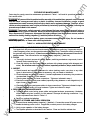
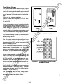
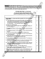
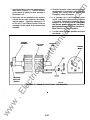
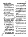
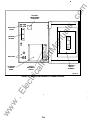
SET SCREW SOCKET SIZE (ACROSS FLATS) I AWARNING I AC power within the cabinet and the rear side of the cabinet door presents a shock hazard that can cause severe perscmal lnjury or death. Disconnect connector J1/P1 before working on the electronic control .system. MINIMUM TORQUE FOR PROPER OPERATION 80 IN-L.BS (9 N•m) 200 IN-L.BS (23 N•m) 2751N-L.BS (31 N•m) 3751N-L.BS (43 N•m) 500 IN-L.BS (57 N•m) 600 IN-L.BS (68 N•m) ua ls 3/16 1N 1/41N 5/161N 3/BIN 1/21N 9/161N Disconnecting J1 /P1 removes all power to the door except for customer-Introduced power at the Signal Module. Be sure to remove all power before replacing components. an No special tools are req uired to remove and re place control system components. w .E lec tri ca lP ar tM The mother board and transformer assembly are held in place by several screws and will not fall when the four screws that secure the Power Sentry cover are removed . Be sure to use all of the hard ware w hen remounting components. ww .c om TABLE 1-2. LUG TIGHTENING REQUIREMENTS REMOVING AND REPLACING ELECTRONIC CONTROL COMPONENTS 1 -1 0