1
Specifications, Front & Rear Panel Descriptions
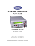
2.2.2 FRONT PANEL OF MODEL 7430
1.
2.
3.
4.
5.
6.
7.
8.
9.
10.
11.
12.
13.
14.
15.
16.
17.
18.
19.
20.
POWER SWITCH: Rocker-style switch
RESET BUTTON: Reset the system before you can proceed to the next test
TEST BUTTON: Press to start the test.
MEMORY KEY: To select one of the 50 memories location.
STEP KEY: To select one of the 8 steps within each memory.
LOCK KEY: To select key lockout mode.
LOCAL/PRINT KEY: To change the operation of the instrument from Remote
to the Local mode. When Printer Port Card is installed, press this key will output
test data to a printer.
AC-W KEY: To select AC Withstand Test
DC-W KEY: To select DC Withstand Test
INSULATION KEY: To select Insulation Resistance Test
GROUND CHECK KEY: To select Ground Check Test
UP-DOWN ARROW KEYS: To scroll the display through the function
parameter menus
SETUP KEY: To enter the setup menu and view or change the GPIB address,
display contrast, alarm volume, PLC remote settings, or the stop on fail setting.
EXIT KEY: To exit any menu or to clear an unwanted entry in a parameter
field.
DATA ENTRY KEYS: To input numeric parameters.
ENTER/REVIEW KEY: To accept numeric data for parameter settings. or
to review up to 8 connected test results after a test has been completed.
HIGH VOLTAGE OUTPUT JACK: HV output, use the high voltage test lead,
model 1101
RETURN OUTPUT JACK: Use the Return test lead, model 1102
GROUND CHECK OUTPUT JACK: Use the Return test model 1102
ANALOG METER : To indicate the High Voltage at the output jack 17
21. SCANNER STATUS LED’s: These LED’s indicate the status of the 8 H.V.
channel
16